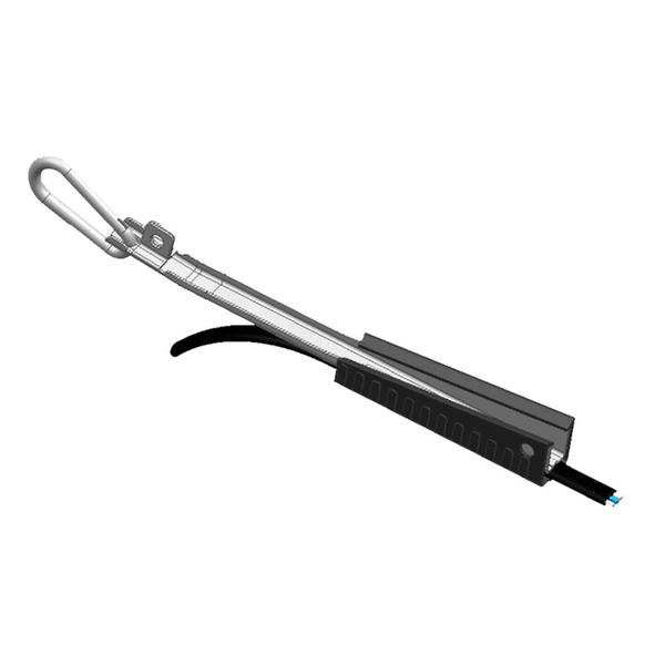
Fiber optic pigtails create connections. Think of these as special wires made of glass, not copper. These cables have a connector already put on at the factory. You will find the other end bare. Fiber optic pigtails help connect different parts of a big. Executive Summary: A fiber optic pigtail is one of the most commonly specified yet least understood components in structured cabling. Get the wrong connector type, the wrong polish, or skip proper fusion splicing technique—and you're looking at elevated signal loss, increased back reflection, and a. A Fiber Pigtail is a single, short, usually tight-buffered, optical fiber that has an optical connector pre-installed on one end and a length of exposed fiber at the other end. Hence the connector side can be linked to equipment and the other side melted with optical fiber cables. It is an economical choice for use in a wide range of applications. ST Fiber Optic Pigtail: This is the most popular connector used for multimode installations and. The core and cladding are the most important parts of any fiber pigtail because they determine how light travels. High-quality fiber pigtail s use ultrapure silica glass for both layers. The core receives additional doping—typically with germanium—to increase its refractive index, allowing light to.
[PDF]
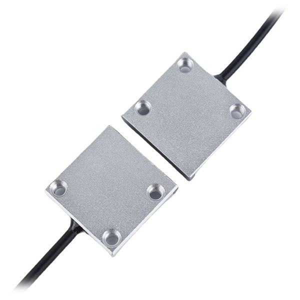
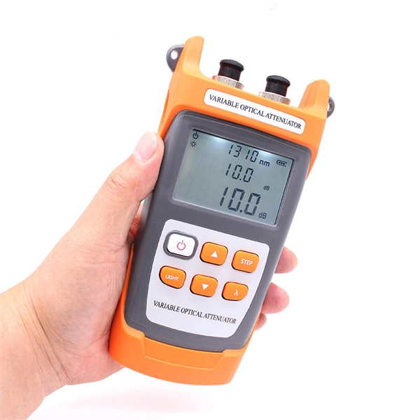
This article explores the different types of Fiber Optic Sensors, their working principles, and various applications. Pricing (USD) Filter the results in the table by unit price based on your quantity. A tariff of 8% may be applied if shipping to the United States. These are reliable and easy-to-use devices that have high power, can automatically adjust to real-time conditions, and have a straightforward display that eliminates any guesswork. This. Check each product page for other buying options. Need help?. Jose Miguel Lopez-Higuera: Handbook of Optical Fiber Sensing Technology, John Wiley & Sons, 2002. P 603 Radiation absorption excites an orbital electron to a higher energy level. Radiation absorption creates electronic excited states that are trapped by localized defects for extended periods of. Fiber optic current sensors are revolutionizing the way electrical currents are measured, providing high sensitivity, immunity to electromagnetic interference (EMI), and the ability to function in harsh environments. We'll delve into Intrinsic, Extrinsic, and Hybrid fiber optic sensors, explaining how they function. A sensor is a device that measures a physical quantity and converts it into a.
[PDF]
This section provides an overview for fiber optic sensors as well as their applications and principles. Also, please take a look at the list of 18 fiber optic sensor manufacturers and their company ranki.
[PDF]

Potential failure modes include shifts in the source wavelength, changes in birefringence of certain optical components due to stress and excessive insertion loss. Degradation can lead to sensor scale factor change, or in extreme cases, to sensor failure. They can utilize fiber-optic sensors for a wide range of applications, from transformers to natural gas pipelines. These tools provide continuous, real-time data along the entire length of the cable. Their small size and light weight make them ideal for promoting grid stability. The power grid is. One undetected anomaly can cause a major failure in high-risk environments like power facilities and the aerospace industry. When human eyes can't see stress fractures or small changes, advanced sensing can detect even minor issues beforehand to maintain safer operations. This study evaluates the metrological performance of shape sensing cables in the presence of fiber core failures, a critical issue in scenarios where cable replacement is impractical. Abstract: Shape sensing with optical fiber sensors is an emerging technology with broad applications across various fields. For many components operated in harsh environments, damp heat is often the most crucial environmental stressor. Fiber optic strain sensors are a type of sensor that uses the principles of light and optical fibers to measure strain.
[PDF]
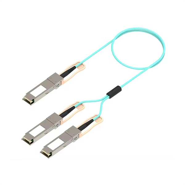
Instead of being hardwired to accept only one type of cable, an SFP+ port accepts small, hot-swappable modules—called transceivers—that you simply slide in and click into place. Need a fiber connection? Pop in a fiber module. Prefer copper? There's a module for that too. A fiber optic transceiver (also called an optical transceiver) is a compact module that both transmits and receives data signals through optical fibers. It serves a dual purpose — transmitting electrical signals as light pulses and receiving light pulses to convert them back into electrical form. An SFP transceiver acts as a compact, hot-swappable optical transceiver that. When building or upgrading a network, many IT managers focus on switches, routers, and access points—while overlooking one critical piece of the puzzle: the optical transceiver. These small modules determine how your uplinks operate: the speed, the distance supported, and whether your Cisco or. Fiber optic cabling is an alternative to copper cabling for data transmission. Popular options include: LC: Common on SFP, SFP+, XFP, QSFP, and SFF transceivers. ST, MT-RJ, and MPO: A bit less common but still in use.
[PDF]
Fiber Internet Hardware: Quick Answer Fiber internet does not use a traditional cable modem. Instead, it requires an Optical Network Terminal (ONT) — a device supplied by your fiber provider that conve.
[PDF]
Calculate end-to-end loss from cable length, connector and splice counts, and known component losses; verify with a light source + power meter (OLTS). If installed loss exceeds design, reduce connection points, rework poor splices, or use optics with better. This document presents a troubleshooting guide for fiber optic cables once deployed and in regular use. It also includes a list of common fault location items. How to troubleshoot: measure. Fiber optic networks are celebrated for their speed and reliability, but even the best systems can encounter problems. When issues like signal loss, slow speeds, or intermittent connectivity arise, systematic troubleshooting is key. These high-speed, high-capacity communication networks are increasingly replacing copper cables, offering superior performance and. Fiber optic troubleshooting is the systematic process of identifying, diagnosing, and resolving problems within fiber optic communication networks. These networks are the backbone of modern data transmission, offering incredible speeds and bandwidth. However, even the most robust systems can. Fiber optic cables are the backbone of today's high-speed communication networks, powering everything from FTTH broadband to data centers. However, like any technology, fiber optic systems can encounter issues that affect performance. Understanding the common causes and solutions helps maintain.
[PDF]
Picking up the best router for fiber internet isn't just about going to the market and choosing one of the best wireless routers. Instead, you need to carefully look at its specs, performance, and the type of securit.
[PDF]

A fiber is used to support G. 691 with a maximum rate of STM-16 or 10Gbit/s and a maximum transmission distance of 40 km (Ethernet) and STM-256 for G. This document outlines the specifications for a single-mode optical fiber and cable designed for use around the 1310 nm zero-dispersion wavelength, suitable for both the 1310 nm and 1550 nm regions, and compatible with analogue and digital transmission. It details the fiber's geometrical, optical. G. 652 is an international standard that describes the geometrical, mechanical, and transmission attributes of a single-mode optical fibre and cable, developed by the Standardization Sector of the International Telecommunication Union (ITU-T) that specifies the most popular type of single-mode. G. 652 optical fiber is a kind of optical fiber that is widely used in the network. 652 is mainly based on the requirements of PMD and the attenuation requirements at 1383nm. 652D is the type of optical fiber in the optical cable, which represents non-dispersion-shifted single-mode fiber, and is currently the most widely used single-mode fiber in China. This article will provide a detailed introduction to the structure, characteristics, and applications of standard single-mode fiber. G652 is a specification for optical fiber cables. It is part of the International Telecommunication Union (ITU-T) G.
[PDF]
Yes. Standard scissors and a ruler will be adequate in most cases, unless you require an exact length of tubing, in which case use a more precise measuring tool. For thicker tubing you may require wire cutt.
[PDF]

Every fiber optic patch cable has a rated attenuation and bandwidth. For example, OM1 is rated at 200 MHz·km at 850 nm and is intended for use in legacy applications. The higher OM ratings provide more speed and distance. Attenuation should remain within acceptable limits for reliable transmission. Executive Summary: Choosing the right fiber patch cable is one of the most consequential decisions in network infrastructure planning. The wrong choice — whether it's an underperforming multimode grade or an unnecessarily expensive singlemode run — can either cripple your network's reliability or. Fiber optic patch cords are key components for efficient, low-loss optical signal transmission between devices and fiber optic cabling links. One or both ends of the patch cord are equipped with standardized fiber optic connectors, and common interfaces include LC, SC, FC, ST, etc. They are manufactured and tested in compliance with TIA 604 (FOCIS), IEC 61754 and YD/T industry standards. OM1, OM2, OM3, OM4, OM5 or OS2 fiber types are available to meet the demand of. Fiber optic patch cables are ideal for supporting high speed telecommunication network fiber applications. They are lengths of optical fiber terminated with connectors on both ends. Their job is to connect two optical devices, like switches, routers, or optical transceivers that communicate.
[PDF]

When you see “PON” on your router, it stands for Passive Optical Network. This light indicates the status of your fiber connection to the network. Passive optical networking (PON), like active optical networking, uses fiber-optic cabling to provide Ethernet connectivity from a main data source to endpoints. While there are many subtle differences, a clear distinction between active optical networking and PON topology is PON's use of a. A passive optical network (PON) is a fiber-optic telecommunications network that uses only unpowered devices to carry signals, as opposed to electronic equipment. In practice, PONs are typically used for the last mile between Internet service providers (ISP) and their customers. The purpose of an OLT is to control, convert signals and coordinate fiber optic service (FiOS) within a PON system. An ONT. Turn off the router and disconnect the power cord. Locate the optical network (PON) port on your router. Inspect the PON cable for make sure that it is correctly connected to the router. Instead of running a separate fiber strand to every home or office, a PON shares a single fiber using optical.
[PDF]
Unlike, single-mode fiber does not exhibit. This is due to the fiber having such a small cross section that only the first mode is transported. Single-mode fibers are therefore better at retaining the fidelity of each light pulse over longer distances than multi-mode fibers. For these reasons, single-mode fibers can have a higher than multi-mode fibers. Equipment for single-mod.
[PDF]