
Fiber optic cable pole brackets and hooks refer to the equipment used for mounting and securing fiber optic cables on utility poles or other vertical structures. (FOA) was founded in 1995 to help develop the workforce to build the fiber optic networks to support a rapid expansion in communications and the Internet. The charter of the FOA was to promote professionalism in fiber optics through education, certification, and. Indoor fiber optic cable uses tighter buffers and routes through conduits or trays. Outdoor fiber optic cable has rugged jackets, gel-filled or water-blocking layers, and armor to resist moisture, rodents, and temperature swings. You install indoor cables in controlled environments. Outdoor fiber. 4. FO-VC2 JOINT USE - VERICAL MIDSPAN CLEARANCES 48. FO-GB GROUNDING AND BONDING 49. FO-RI JOINT USE RISER. Our Fiber Optic Mounting Hardware category includes essential components designed to secure, organize, and protect fiber optic cables and equipment. Proper mounting hardware is crucial for efficient cable management, strain relief, and long-term network stability. However, installing fiber cables in outdoor environments exposes them to harsh weather conditions such as rain, thunderstorms, and freezing temperatures.
[PDF]
No, a 10G SFP (Small Form-factor Pluggable) module is designed to operate at 10 Gigabits per second (Gbps) and is not compatible with a 1 Gigabit per second (Gb) port. Therefore, a 10G SFP module will not work. When SFP optical module is inserted into the SFP port of Gigabit switch with fiber optic patch cable or copper cable, it can realize different distance transmission. For example, the maximum transmission distance is 160 km when using SFP1G-ZXC-55 optical module and LC duplex fiber patch cable, and. 10 Gigabit Ethernet (10GE, 10GbE, or 10 GigE) is a group of computer networking technologies for transmitting Ethernet frames at a rate of 10 gigabits per second. It was first defined by the IEEE 802. For example, when using the AE-SFP-ZX160 optical module and LC duplex fiber optic patch cords, the maximum transmission. Can 1G SFP optics work with 10Gb SFP+ ports on a 10Gb switch, or vice versa? This comprehensive guide reveals the intricacies of SFP and SFP+ compatibility and provides useful solutions for network switch users. Can 1G SFP Optics Run at 10G SFP+ Port? Can 10G SFP+ Optics Run at 1G SFP Port? Can. Small form-factor pluggable or SFP Modules can be described as compact and hot-pluggable hardware that connects various networking devices such as servers, routers, and switches. Networking standards, including Ethernet, Fiber Channel, and SONET, are also used with the SFP modules, broadening their.
[PDF]

These data switches are responsible for routing and data switching at the core layer of the network. The data routed and switched by the core switch is carried forward to the bottom layers of the network such as the distribution and access layer. Engineered to aggregate massive volumes of data from distribution switches, it provides ultra-low latency and maximum throughput to ensure uninterrupted routing and packet. The significance of the core switch in building and sustaining a resilient network infrastructure is paramount. This determines network efficacy, dependability, and the speed at which. There are different types of enterprise switches that perform various roles in these layer-based or hierarchical ethernet networks. The hierarchy Ethernet network. A core switch in networking serves as the high-capacity backbone, italic centralizing data flow and ensuring efficient communication between different network segments. Simply put, it's the kingpin that keeps your network humming. You may also want to know: Can a Nintendo Switch Play DS Games? ·. A core switch is the backbone of a large-scale network, designed to handle massive volumes of traffic with ultra-low latency and maximum reliability.
[PDF]
The various protective functions available on a given relay are denoted by standard. For example, a relay including function 51 would be a timed overcurrent protective relay. An overcurrent relay is a type of protective relay which operates when the load current exceeds a pickup value. It is of two types: instantaneous over current (IOC) relay and definite time overcurrent (DTOC) relay.
[PDF]

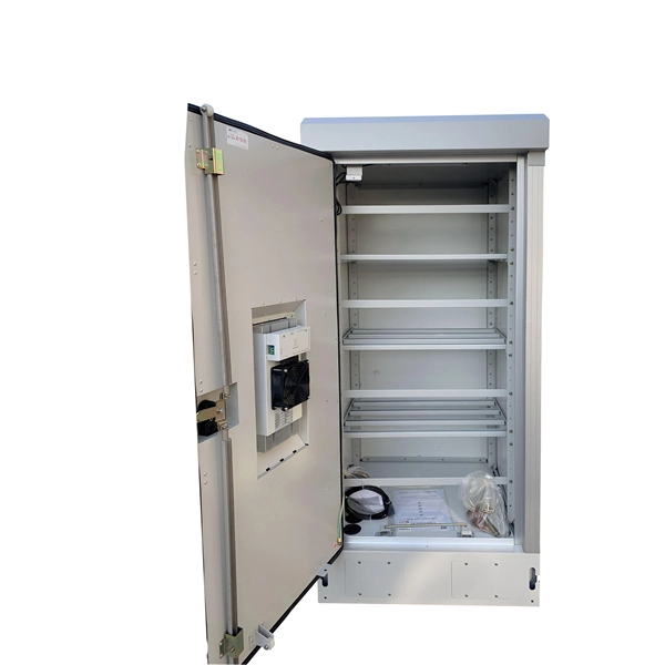
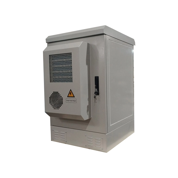
More specifically, these systems keep tabs on voltage, current, and temperature limits and control the disconnect relay. This allows them to disconnect themselves from the external application in case of malfunction. From a drop of rain to the shining sea, an energy storage system is like the earth's bodies of water (hear us out). In a battery energy storage system (BESS), the energy in the battery cells is like raindrops that combine to form a brook. Made of the combined energy from cells, these brooks combine. Battery energy storage systems (BESSs) investment is expected to grow to $103 billion by 2030. ) Battery systems aren't just designed to serve as local power backups, such as the systems used to power critical facilities (including hospitals and data centers) when the normal. When a 300 MWh battery energy storage system (BESS) in Arizona tripped offline during July's heatwave, operators discovered voltage fluctuations had overwhelmed its protection relays. Could your facility withstand such stress? As global BESS installations surge—projected to reach 1. Protection is necessary when energy and voltages combine from the modules, as well as from the battery racks. Fuses are an efficient. The electrical integration design of a Battery Energy Storage System (BESS) is based on the application scenario and includes various aspects such as DC, high/low voltage distribution, control power distribution, grounding, lightning protection, and safety standards.
[PDF]

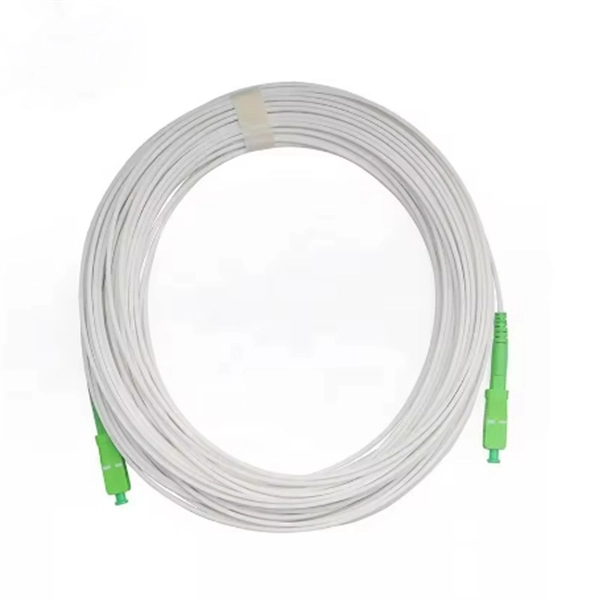
The optical fiber cold joint is used when two pigtails are docked. The main part inside it is a precise V-shaped groove. It is used to connect optical fiber or optical fiber butt pigtail, which is equivalent to making a joint (fiber butt pigtail refers to the butt joint of the fiber core of the optical fiber and the pigtail instead of the pigtail head mentioned in the former), and is used for this kind of cold. When installing a fiber optic network, connectors are required to connect both ends of the fiber optic cable. Common splicing methods include optical fiber cold splicing and optical cable hot fusion splicing. Advantages and disadvantages of fiber optic cold splicing Fiber cold splicing refers to. Mechanical splicing involves physically aligning and holding two fiber ends together using mechanical means. This method is typically used for permanent connections, but it allows for disassembly without damaging the fiber ends. Mechanical splices are often preferred for their simplicity and. Optical fiber transmission offers numerous advantages, including a wide frequency bandwidth, high communication capacity, low signal loss, immunity to electromagnetic interference, compact cable size, and the availability of abundant raw materials. As a result, it has become a preferred medium for. Executive Summary: A fiber optic pigtail is one of the most commonly specified yet least understood components in structured cabling.
[PDF]

A lighting control module operates as the central controller for a lighting system. It receives input from switches, apps, or sensors and regulates electrical flow to connected lights. Depending on the setup, it adjusts brightness, color temperature, or full lighting scenes. It acts as a bridge between your physical lighting fixtures and the smart systems that manage them. Instead of relying solely on traditional wall switches, you can control your lights via remotes, mobile or web apps. A lighting control module is an essential component in a lighting control system that manages how lights are powered, dimmed, or switched on and off. Think of it as the “brain” that receives commands—either from a manual switch, a sensor, or a building automation system—and translates them into. A lighting control module is a smart device that manages lighting circuits, adjusting brightness, automating schedules, and responding to sensors. It enhances comfort, efficiency, and ambience in homes and commercial spaces. Explore the multifaceted benefits and applications of lighting control modules, from home automation to industrial. These modules are designed to communicate with various sensors, switches, and control panels, making lighting adaptable to different environments and user preferences. It enables precise management of lighting systems, allowing for adjustments in brightness, color, timing, and even integration with other smart devices. This innovation.
[PDF]
The voltage in Turkmenistan is 230 volts and the frequency is 50 Hz. Turkmenistan has standardized on type C and type F sockets and plugs. Type E plugs can also be used thanks to their compatibility with type F sockets. If your device plugs don't match Turkmenistan's standards, we recommend purchasing suitable travel adapters in advance to ensure proper use. What power plug types are used in Turkmenistan? Plug type B. Ok, you are going to Turkmenistan, you will use power plugs/outlets similar to the following picture (s): (includes Ashgabat, Mary, Turkmenabat, Dashogus, Konye-Urgench, Turkmenbashi. (more details after you choose where. Everything you need to know about Turkmenistan power outlets, plugs for Turkmenistan, power adapters, voltage, and frequency when travelling to Turkmenistan. Planning a trip to Turkmenistan and wondering if you need a power adapter? Look no further! We've got you covered with this comprehensive. Turkmenistan uses power outlets and plugs of types C & F. Take a look at the pictures below to see what these plugs and power sockets look like: Doesn't look familiar? Do the outlets look different in your country? You'll need a power plug adapter. 220 V has an advantage over lower voltage such as the 110 V that it is cheaper to transmit. On the other hand, 220 V is more dangerous than lower voltages.
[PDF]

Precision begins with a quality optical encoder disc in the automation, robotics, and motion control systems of today. This tiny yet essential device transforms physical movement into exact digital signals that dictate speed, position, and direction. What constitutes an optical transceiver? An optical transceiver, a crucial device utilized in optical communication, is an optoelectronic element, allowing the interconversion of optical and electrical signals during the information transmission. It generally has the components for transmission. Therefore, NASA is developing optical communications to address limitations of radio frequency (RF) communications, including: bandwidth, spectrum and overall size of frequency packages and power used. Optical spectrum uses light as a means of transmitting information via lasers. Optical. Optical transceivers are devices that convert electrical signals into optical signals and vice versa, playing a key role in supporting modern high-speed communication networks. They are widely used in data centers and communication systems to enable high-speed, efficient transmission of large. Optical transceiver modules are designed and built by a variety of manufacturers. In the design of optical transceivers, the selection of channel configuration and modulation.
[PDF]
FTTH Networks: Wall-mount panels are used in apartment basements to distribute signals to individual units. Data Centers: High-density 4U panels are used for Top-of-Rack (ToR) switching. Broadcast & Media: Used for high-bandwidth 4K/8K video signal routing. This 2026 expert guide explains the functions, placement, structure, and application scenarios of ODFs and fiber patch panels-and includes a deep engineering FAQ that resolves real-world deployment challenges. Where Do ODF and Fiber Patch Panels Fit in a Modern Fiber Network? To understand the. Depending on different network construction scales and application environments, fiber optic cabinets and patch panels are typically used in various combinations. Choosing the right structural combination can significantly improve network construction efficiency. First is the standard. A Fiber Optic Patch Panel, also known as an Optical Distribution Frame (ODF) or fiber termination enclosure, is a centralized hardware unit designed to manage, protect, and organize fiber optic cable connections.
[PDF]

Optical couplers can split or join signals in fibers. You can connect many users to one port with 1:n or 2:n splitters. These devices work both ways, which helps strong network communication. They help send. This small device connects or joins optical fibers together. It helps networks grow and change when needed. Learn about the two main types of fiber optic couplers: fused and planar. Fused. How to Choose the Right Fiber Coupler (FTTH, Data Center & More) Are you in the process of designing a Fiber to the Home (FTTH) network, but wondering how to split one fiber for multiple users? Or maybe you are operating a data center, and you would like to use a single signal to provide to. Fiber optic couplers are optical devices that connect three or more fiber ends, dividing one input between two or more outputs, or combining two or more inputs into one output. The device allows the transmission of light waves through multiple paths. Fiber optic couplers can either be passive or. A fiber optic coupler is a passive optical component that splits, combines, taps, or redistributes light between optical fibers. In real-world networks, couplers let one signal reach many users, allow several signals to share one fiber path, or sample a small amount of light for monitoring. 5/125 µm fiber, with low insertion loss and a broad operating wavelength range from 800 to 1600 nm. The 1x2 and 2x2.
[PDF]

In this article, we will explore the specifications for household distribution boxes and provide guidance on how to install them correctly. Whether you're an electrician or a DIY enthusiast, this guide will help you understand the basics of home electrical distribution. more Welcome to our. A distribution box is the heart of any electrical system. It takes the incoming power and safely distributes it to different circuits throughout your building. While many families are familiar with these boxes, there is often a lack of understanding regarding their specifications and proper. Strictly speaking, the word “Distribution Box (D-box)” can refer to two categories: electrical distribution boxes and septic tank distribution boxes. This article mainly talks about the first one. An electrical distribution box, also known as a power distribution box, panelboard, or consumer unit. Electrical wiring powers everything in your home, from lights and outlets to major appliances. Whether you're building new or updating an older system, the way your wiring is planned and installed affects how safely and efficiently everything runs. We'll break down the key parts of a home. This article is going to be very helpful for you, if you want to learn about how appliances, Motors, Generators, Light bulbs, circuit breakers, float switch, and Contactors are wired up.
[PDF]

In this video, we'll show you how to connect an energy meter to a distribution board (DB) safely and efficiently. energy meter connection with distribution box How to Connect an Energy Meter to Your Distribution Box Easily Steps to Properly Connect Your Energy Meter to a Distribution Box. Then I fix the box securely, route and terminate cables neatly, seal against weather, label clearly, and verify all connections before the utility energizes the service. I. Step-by-step guide to installing an electric meter box. Learn safety tips, wiring steps, troubleshooting, and when to call a pro. An electric meter box measures how much electricity your home uses. It helps the utility company give you the right bill. Installing an electric meter box might seem like a job for professionals only—but with the right knowledge, it's a task many homeowners. When your newly constructed or renovated home is ready for electric service, the power company will have to install an electric meter to monitor your electricity usage. The meter belongs to the power company, and it is responsible for installing it, but the electric meter box that contains it (also. Always begin with disconnecting the main supply before accessing any enclosure containing distribution components. This prevents arc faults and ensures safety when modifying or inspecting current paths.
[PDF]
