The zero-buoyancy rov cable was born as a power connection and control of underwater robot equipment, as well as signal transmission and feedback link cable applications. The zero-buoyancy cable has been tested by the market and practice due to its excellent. The global underwater zero buoyancy cable market is experiencing robust growth, driven by the expanding offshore energy sector, increasing demand for subsea infrastructure development, and advancements in underwater communication technologies. Linden Photonics is renowned for its innovative fiber-optic solutions, specifically designed for Remote Operated Vehicles (ROVs). These ROV tethers are crucial in underwater applications, offering high performance, durability, and reliability in challenging environments. For use with ROV's (Remote.. Customizable neutral buoyancy fiber optic power cable for ROVs and underwater drones. High‑performance hybrid design combining power and data in one composite cable. Engineered for seawater resistance, flexibility and subsea reliability. Suitable for inspection systems, subsea cameras and. At Invocean, we understand the increasing demands and the critical nature of Remotely Operated Vehicles (ROVs) in various industries such as underwater construction, surveillance, salvage, and scientific research. To support these high-performance tasks, ROVs and Micro-ROV's require reliable.
[PDF]

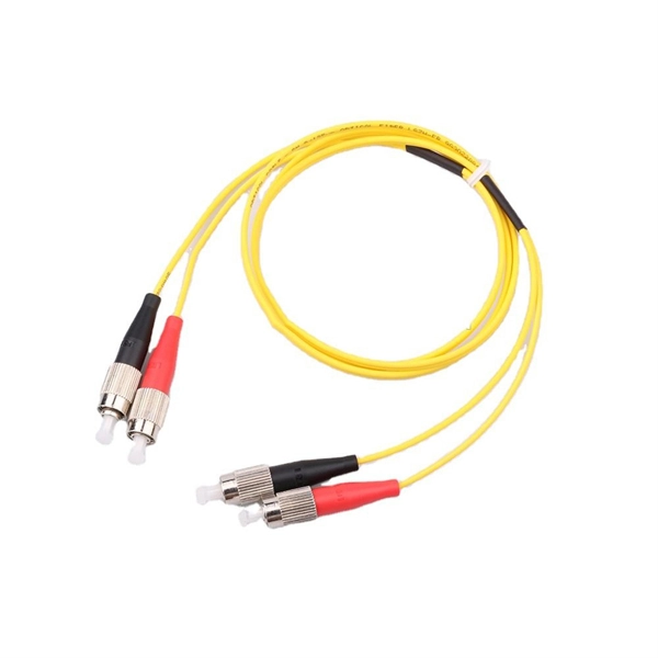
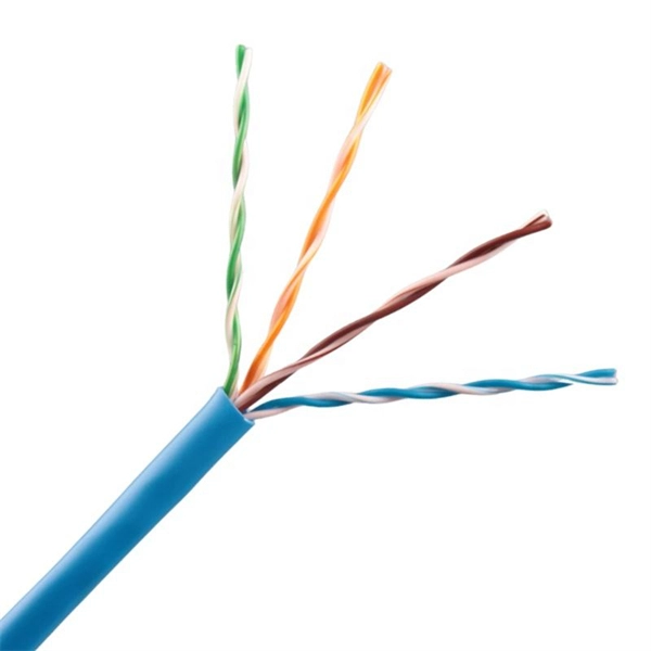
This article provides a detailed technical comparison between fiber optic and copper cables, offering a clear perspective for engineers, network architects, and procurement managers. The core distinction between the two technologies lies in the physics of data. However, the exponential growth in data demand has positioned fiber optic technology as the superior alternative for performance, scalability, and future-readiness., 10G/25G/40G/100G and beyond depending on optics and reach). Copper Ethernet scales too, but practical limits are lower and depend. The two main options are fiber optic cables and copper cables, each with its own advantages and drawbacks. Fiber optic cables are praised for their high performance and scalability, while copper cables remain a cost-effective choice, especially for budget-conscious projects and older systems. Copper wire is more susceptible to interference and has limited data capacity, making optical fiber the preferred choice for modern high-speed. Optical connectivity, utilizing fiber-optic technology, has emerged as the superior choice for modern networking, offering unparalleled performance, reliability, and scalability. For example, a typical 10 Gbps copper Ethernet link (such as Cat 6A) over 100 meters can consume approximately 5 to 8+.
[PDF]
Hot-dip galvanized cable trays undergo a galvanization process where the steel tray is immersed in a bath of molten zinc. The process involves several steps, including surface preparation, zinc alloy formation, and cooling. In the case of outdoor or salty air, we apply the Hot-Dip Galvanizing. We immerse the tray that is done into a huge container of molten zinc at a temperature of approximately 450 C. This envelops every corner and edge in a thick protective layer. They feature convenient overall installation, a reasonable structure, a long service life, and an aesthetic appearance. Cables installed in fire-resistant cable. Here's why cable trays matter: Organization: They help organize cables neatly, preventing tangling or damage. Protection: They protect cables from being damaged by external factors like dirt, dust, and accidental impacts. Easy Maintenance: With cables clearly laid out and supported, repairs or. Fireproof galvanized spray-painted cable tray is a composite structure made entirely of steel. This advanced procedure ensures each tray is un. Ladder Type Cable Tray – Consists of two side rails connected with rungs spaced at regular intervals, designed for heavy-duty applications.
[PDF]
In this guide, you will find a chronological description of the fusion splicing process, the principal technical standards, and answers to the real-life questions network engineers and procurement teams may have. TMM P021 OPTIC FIBRE CABLE JOINING, TERMINATION & MANAGEMENT Version 9. Therefore, we will also touch on cost factors, risk management, and best practices in. Fusion Splicing • Splicing is the process of connecting two bare fibres directly without any connectors. • Splicing provide much lower insertion loss compared to fiber connectors that's why Splicing is preferred over the use of Connectors. Fiber mechanical splicing – Insertion loss < 0. 5dB Fiber. What is Fiber Optic Splicing and Why is it Needed? – #1. Ensure Your Splicing Tools are Clean – #2. 56 was approved by ITU-T Study Group 6 (2001-2004) under the ITU-T Recommendation A. 8 procedure on 14 May 2003. The International Telecommunication Union (ITU) is the United Nations specialized agency in the field of telecommunications. By following the step-by-step guide provided, you can effectively perform fusion splicing to maintain high-quality fiber optic.
[PDF]

Optical cables are born from ultra-pure glass preforms, drawn into hair-thin fibers, coated for protection, bundled strategically, and encased in durable jackets. This meticulous process ensures light-speed data transmission with minimal loss. Fiber optic cables are the backbone of today's high-speed internet, telecommunication systems, and data transfer technologies. With the increasing demand for faster and more reliable connectivity, the construction of optical fiber cable factories has become essential. In this guide, we will. The Modified Chemical Vapor Deposition (MCVD) process was developed in 1974 at Bell Labs to improve traditional Chemical Vapor Deposition (CVD) methods for fabricating optical fibers. In MCVD, a quartz tube is used as the initial substrate or source material. Fiber optic technology has revolutionized the way information is transmitted, offering numerous advantages over traditional copper wiring. What makes fiber optic cables special is their ability to. Single-mode fiber represents the pinnacle of long-distance optical transmission technology. At Sinoptec, our advanced manufacturing processes ensure each fiber meets rigorous.
[PDF]

This video takes you through our highly automated cable tray machine production line. You'll witness how a coil of metal strip is transformed into standardized, ready-to-install cable trays through a series of precision processes. Understanding the intricate world of cable tray manufacturing reveals the sophisticated processes, quality standards, and technical expertise required to produce these essential electrical infrastructure components that power our modern world. The foundation of quality cable tray production begins. HCM-600 Cable Tray Automatic Production Line is a cable tray roll forming line that adopts metal sheet coils as raw material. It forms the sheet into specific shapes and specifications through decoiling, leveling, punching, notching, and roll forming. Together. Producing cable trays involves a detailed and precise process aimed at creating a robust and efficient system for managing electrical cables. These trays are used in various industries for organizing cables that carry power, control signals, or communication lines. Brilltech Engineers Pvt. Ltd is one of the trusted Cable Tray Manufacturers in Chad and brings you the products as per the need of your.
[PDF]

Clear guide to identifying and disconnecting internal computer cables with labeled diagrams. Learn how to safely handle and remove each connector step by step. In this guide, you will learn the essential computer parts names with labeled pictures and short explanations so you can quickly identify each part on a real computer. The focus stays on the components people encounter most, from the hardware inside the case to the devices on your desk. By the end. There are so many types of cables these days that a beginner will be completely lost in the tech jungle. Just which connector is which? Read on to find out! Before going into the types of cables, let us start with some basic trivial information that may be useful. Computer cables are not random. An essential aspect of modern computer room design is cable management, which involves organizing and protecting the cables connecting various equipment pieces. Optimal cable management keeps cables hidden and out of the way to protect the equipment they support and the employees around them. Static electricity can damage sensitive parts, so wear an anti-static wristband or ground yourself before proceeding. Remove the side panel by loosening the screws at the rear of the chassis, then gently sliding the. Check each product page for other buying options. As a result, the cable is wide and flat. Ribbon cables are usually seen for internal peripherals in computers, such as hard.
[PDF]
The Price list N 08/2024 - Cables for domestic and industrial applications is applicable starting August 1th 2024 and replaces the former one, Price list N 02/2023. All prices are given per 1000 meters. The Price list is made available as an excel file, in French and Dutch only. Please note our. Vibration Sensors Top exit, 105 C, 4-20 mA ( 5% @ full scale) proportional to Velocity, RMS, 5. 0 ips (127 mm/sec), 1/4-28 mounting hole (stud included), MIL-C-5015 connector. 0 ips (127 mm/sec), 1/4-28. You are here: Home / Catalog / Condition Monitoring / Vibration Monitoring Sensors, Accelerometers, Modules, Cables and Mounting. Quality products and a competent friendly service goes a long way! Thank you to the teams at RMS and Hansford. We offer a comprehensive range of Vibration Monitoring. Fiber optic acoustic sensing cable, extra small, with stainless steel central metal loose tube, stainless steel strength members and PA outer sheath, good acoustic response, for up to 4 fibers. Professional cables and connectors for AV/broadcast.
[PDF]
When it comes to testing fiber optic cables, a Visual Fault Locator (VFL) is an essential tool in your toolkit. A VFL is used to detect faults, breaks, or bends in fiber optic cables by emitting a bright red light that is visible even through the fiber's jacket. Let's dive into everything you need to know about mastering VFLs. In the. Finding a break in a fiber optic cable can be challenging but is essential for maintaining a stable network. Common Indicators of a Cable Break Signal. Here Kingfisher's experienced engineers share their experience in best practices and procedures for fiber optic testing related mostly to installation and maintenance. We hope that by sharing our knowledge, we will help grow our industry. Please enjoy & pass on these notes. The following are key methods and techniques used for optical fiber cable line failure positioning: Visual Inspection: Perform a visual inspection of the. Locating faults in fiber optic cables requires specialized tools and techniques. Look for dirt, scratches, or damage on the connectors. Clean. To ensure the quality and continuity of fiber optic services, it is essential to identify and locate fiber optic cable faults as quickly and accurately as possible. In this article, you will learn about some of the common methods and tools for fiber optic testing and troubleshooting.
[PDF]

Central operating wavelength is a term used to describe the nominal value of the wavelength of light that is generated by a cable. It is the wavelength at which the majority of the optical power generated by the cable is concentrated, and is determined by measuring the peak power of. Light in optical fiber travels in the near-infrared region, far beyond visible light, and choosing the right transmission wavelengths is fundamental for minimizing loss and maximizing bandwidth. This article delves into why 850, 1310, and 1550 nm are standard, what less-known regimes and tradeoffs. Fiber optic transmission wavelengths are determined by two factors: longer wavelengths in the infrared for lower loss in the glass fiber and at wavelengths which are between the absorption bands. Thus the normal wavelengths are 850, 1300 and 1550 nm. Fortunately, we are also able to make. The OS1 designation refers to the cable's optical specifications, specifically its attenuation characteristics. OS1 cables have a maximum attenuation of 0. This standardization ensures interoperability between different manufacturers' equipment and facilitates the global deployment of fiber optic networks. Bandwidth refers to the capacity of a fiber optic cable to transmit data — much like the width of a highway determines how many vehicles can pass through at once. Typically measured in gigahertz (GHz) or gigabits per second (Gbps), it indicates the maximum amount of data that can flow through the.
[PDF]

This article outlines five specific steps for repair: 1) Identify the break; 2) Cut out the damaged section; 3) Strip the cable; 4) Trim the fiber ends; 5) Test the repair. DIY fiber optic cable repair kits are increasingly popular for those who prefer home repairs. This guide covers the essential tools and step-by-step procedures for low-loss fiber optic cable repair. Construction Activities: Accidental damage during construction. While a cut or damaged fiber optic cable can temporarily take your network down, it is possible to quickly fix the cable with the right tools. This wikiHow article will teach you how to splice a cut fiber optic cable back together with a fiber optic stripper and cutter and a fiber optic crimper. These cables consist of a core (glass or plastic) that carries light signals, surrounded by cladding to reflect light inward, a buffer for protection, and an outer jacket for durability. The actual steps may vary depending on the cable and/or connectors. Fiber optic cables are typically damaged in one of two ways: A premade fiber optic cable suffers connector damage when too. Don't let cable woes ruin your streaming binge or video conference; instead, explore these six proven ways to troubleshoot and fix your optical cable issues. Before diving into solutions, it's crucial to understand what an optical cable is and how it works. Begin by identifying the damage, which can be done using an Optical Time Domain.
[PDF]

This Code consists of the introduction, definitions, grounding rules, lists of referenced and bibliographic documents, and Parts 1, 2, 3, and 4 of the 2023 Edition of the National Electrical Safety Code. The Institute of Electrical and Electronics Engineers, Inc. 3 Park Avenue, New York, NY. Climbing Space is an unobstructed, vertical space along the side or corner of the pole. In gen-eral, it consists of an imaginary box, 30-inches square, extending at least 40 inches above the highest communications cable or other facility and 40 inches below the lowest communications cable or other. The Fiber Optic Association, Inc. (FOA) was founded in 1995 to help develop the workforce to build the fiber optic networks to support a rapid expansion in communications and the Internet. The charter of the FOA was to promote professionalism in fiber optics through education, certification, and. There are a number of ways of finding out more about cabling standards. You can buy a complete copy of the EIA/TIA or ISO/IEC standards which can be very expensive and wade through page after page of standards language. You can also get catalogs and/or visit the websites of a number of cabling. to n utral comm.
[PDF]
Genuine Modules mentions that the cost of fiber optics per kilometer can range from $10,000 to $50,000, depending on various factors such as the type of fiber, installation method, terrain, and region. Fiber-optic cable materials typically cost $1 to $6 per linear foot, depending on fiber count and cable type. Commercial building installations with 100-200 network drops generally range from $15,000 to $30,000. Single-mode fiber costs less per foot than multimode fiber, but it requires more. The price of fiber optic cabling depends on cable type, length, installation method, and surrounding materials. Typical costs hinge on fiber count, indoor versus outdoor use, and whether trenching, splicing, or termination is required. This guide provides practical ranges in USD and practical price. Discover 6 core fiber optic cable 1km price with GYXTW armored outdoor design, G652D fiber, CE/ROHS, ideal for 5G FTTH networks. Knowing how much fiber optic cable costs, which factors can impact cost, and key cost considerations can help you avoid unnecessary expense and get the most out of your budget. 50 per meter, depending on several variables. Here's a general pricing reference: These are indicative prices based on standard configurations. Custom-built cables or niche specifications can lead to higher prices. 30Single-mode Outdoor Cable$0. 50Multimode (OM1/OM2/OM3)$0.
[PDF]