At its core, an overcurrent relay operates on a very simple concept: detect excessive current, then trip fast and isolate the fault. When current surpasses the relay's pickup setting, an internal mechanism triggers the circuit breaker. IEEE/IAS/I&CPSD Protection & Coordination WG Chair Jacobs Canada, Calgary, AB rasheek. com IEEE Southern Alberta Section PES/IAS Joint Chapter Technical Seminar - November 2016 Protective Relays - Technical Seminar Nov 2016 - Copyright: IEEE 2 Abstract: Protective relays and devices. Relay protection against high current was the earliest relay protection mechanism to develop. From this basic method, the graded overcurrent relay protection system, a discriminative short circuit protection, has been formulated. Types of over current relay. It is really current monitoring relay. Overcurrent Relay Definition: An overcurrent relay is a protective device that operates solely based on current without the need for a voltage coil. These relays are known for their speedy operation during a fault and are hence used widely in high-voltage applications. Let's know in. The Art and Science of Protective Relaying, by C. Mason, John Wiley and Sons, 1956. Evaluation of Distribution System Relaying Methods, by A. McConnell, Presented at the Pennsylvania Elec-tric Association, May 16-17, 1957.
[PDF]

These numerical codes, ranging from 1 to 99, uniquely identify the functions of protective relays, associated devices, and control equipment in electrical power systems. In electric power systems and industrial automation, ANSI Device Numbers can be used to identify equipment and devices in a system such as relays, circuit breakers, or instruments. The device numbers are enumerated in ANSI / IEEE Standard C37. 2 Standard for Electrical Power System Device Function. According to the ANSI/IEEE standards, device function numbers are crucial identifiers in power system protection and control engineering. ANSI IEEE Standard Device Numbers are below: (the more commonly used ones are in bold) 86T is a Lockout Relay for a. The widely used United Sates standard ANSI/IEEE C37. Even in those parts of the world where IEC standards are predominate, the use of ANSI numbering. For power grid systems, ANSI and IEEE functional number codes dictate the use and restrictions of both the devices themselves, as well as the functions of those devices within the scope of a circuit. These devices include switches, disconnects, circuit breakers, generators, and motors. Instead of verbal descriptions, we use numbers to describe the functions of a relay. Why use numbers instead of words? Efficiency.
[PDF]

What is a Full Wave Rectification? Full wave rectifications are a specific type of rectification that transforms the entire AC signal cycle into a pulsing DC signal, one half at a time. Full-wave rectification converts alternating current to DC using numerous diodes. The full wave rectifier converts both halves of each waveform cycle into pulsating DC signal using four rectification diodes. In the previous power diodes tutorial we discussed ways of reducing the ripple or voltage variations on a direct DC voltage by connecting smoothing capacitors across the. Full Wave Rectifier Definition: A full wave rectifier is defined as a device that converts both halves of an AC waveform into a continuous DC signal. Circuit Diagram: The circuit diagrams for both centre-tapped and bridge rectifiers show how diodes are used to ensure the conversion of AC to DC. For the conversion of AC voltage into DC voltage it uses two different types of circuit configurations i. Center Tapped Full Wave Rectifier and Full Wave Bridge Rectifier. Output Voltage: Produces a pulsating DC output with twice the frequency of the. The process of converting the AC current into DC current is called rectification. Rectifiers are generally classified into two types: half wave.
[PDF]
Home appliances TV sets, VCR, Microwave ovens Office machines Industrial equipment NC machines, Robots, Temperature controllers Photocopiers, Vending machines. Space saving design Wiring can be done with ease (DIN terminal). N.C. contact raw N.O. contact raw COM contact raw Coil terminal raw. N.C. contact raw N.O. contact raw COM contact raw Coil terminal raw. For Cautions for Use, see Relay Technical Information.
[PDF]

This guide describes the general requirements, functional and technical performance requirements, test requirements, labeling and packaging requirements, transportation and storage requirements, supply integrity requirements, and quality assurance requirements for hybrid high-voltage. This guide describes the general requirements, functional and technical performance requirements, test requirements, labeling and packaging requirements, transportation and storage requirements, supply integrity requirements, and quality assurance requirements for hybrid high-voltage. Guide for Technical Requirements for Hybrid High-Voltage Direct Current Transmission Protection and Control Equipment This guide describes the general requirements, functional and technical performance requirements, test requirements, labeling and packaging requirements, transportation and storage. purpose of this white paper is to aid WECC members (Specifier) in specifying and applying relay systems that will provide adequate protection of extra-high voltage (EHV) on 345-kV or higher transmission lines and comply with the NERC Reliability Standards. The recommendations in this white paper.
[PDF]

Protective relays are essential devices used in electrical power systems to detect faults and abnormal conditions, initiating corrective actions to prevent equipment damage and ensure system stability. These relays play a crucial role in the protection of transformers, generators, transmission. A protective relay is an intelligent device that senses abnormal electrical conditions, such as overcurrent, under-voltage, or frequency deviations. It initiates the operation of circuit breakers to isolate the affected section. This prevents damage to equipment, reduces downtime, and safeguards. Protective relays are critical components in power systems, providing essential protection for various elements such as generator sets, outgoing feeder and load networks, and incoming utility sources. It functions as a watchdog by constantly surveying multiple system components including voltage, current, frequency, and phase angle. It. Protective relays and devices have been developed over 100 years ago to provide “lastline”of defense for the electrical systems. They are intended to quickly identify a fault and isolate it so the balance of the system continue to run under normal conditions. The selection and applications of.
[PDF]
The best router for fiber internet is one that matches your plan speed, home size, and how you use your connection. Our top overall pick is the Netgear Nighthawk RS700S, a Wi-Fi 7 router built for multi-gig fiber plans that handles up to 200 devices across 3,500 square feet. Keep reading for a rundown of the best fiber optic internet routers in 2026. After providing you with the general image about the eight best routers for fiber internet. A fiber-optic connection is the best choice for fast home internet as it has a number of advantages compared to traditional copper cables, such as faster speeds and less interference. For budget-conscious. Instead of using your old router, a high-performance Wi-Fi router designed for fiber optic internet will ensure you seamless streaming, online gaming, and remote work all over your space. However, the market is flooded with countless options, making the selection quite overwhelming. During testing, it provided perfect coverage. Amazon eero 6+ mesh wifi router - Supports internet plans up to a Gigabit, Coverage up to 1,500 sq. 5 Gbps, Coverage up to.
[PDF]
The formula for calculating electrical box size is: [ BS = (N times D) + A ] Where: ( BS ) is the box size in cubic inches. ( N ) is the total number of conductors. ( A ) is the volume allowance for any device or fitting. This electrical box fill calculator (or in short, box fill calculator) will help you determine the total box fill volumes you will need to meet so that each of your electrical utility boxes will pass the National Electrical Code®. In this calculator, you will learn: How to use electrical box fill. Choosing the correct electrical box dimensions is essential for safe wiring, code compliance, and long-term reliability. Whether you are installing outlets, switches, lighting fixtures, or junction connections, box size directly affects wire fill capacity, device fit, and installation quality. This ensures compliance with electrical codes and prevents overcrowding. The size of the box is determined by the number and size of the wires, devices, and fittings that will be contained within it. In this article, we'll.
[PDF]

Among the most important emerging trends in fiber optic technology for 2025 are: Ultra-low loss (ULL) fiber, extending long-distance data transmission with minimal signal degradation. Bend-insensitive fiber, delivering reliable performance in tight urban and data center installations. With speeds reaching 100Gbps, 400Gbps, 800Gbps, and. According to a recent study by the Fiber Broadband Association and RVA, 76. 5%) are now serviceable by fiber—an increase of 13% in 2024. By 2028, fiber is expected to reach 80% of U. As the industry looks ahead, six major trends are shaping the future of fiber. The global FTTH market size is estimated at $47 billion in 2022 and is projected toward upward growth at a compound annual growth rate (CAGR) of 12% from 2023 to 2030. Born of a wildly successful experiment The evolution of FTTH networks dates to the 1970s, to an experiment with fused silica. The. From multi-gigabit speeds to open-access models and AI-driven optimization, what's on the horizon suggests that the fiber broadband industry is not just growing – it's transforming. Continued Expansion in Global Coverage The. The future of Fiber Optic communication is on the brink of remarkable advancements, setting the stage for groundbreaking innovations that will shape our daily lives. From enabling high-speed internet connections to.
[PDF]
In, a single-mode optical fiber, also known as fundamental- or mono-mode, is an designed to carry only a single of light - the. Modes are the possible solutions of the for waves, which is obtained by combining and the boundary conditions. These modes define the way the wave travels through space, i.e. how the wave is distributed in space. Waves can have the same mode but have different frequencies. This is the case i.
[PDF]

In this context, Rastriya Prasaran Grid Co Ltd (RPGCL) was established by the Government of Nepal on 12 July 2015 to transmit and evacuate the power for the development and operation of the hydropower sector. The Company's corporate office is located at Kathmandu. Our Products are manufactured from high quality raw materials and all our products are certified with international Standards. To know more about us please contact us at info@ktcgroup. np/ +977-21-572485/86/87. We are committed to providing our customers with an eclectic array of products to. The Rathi ECO LED Bulb is available in a range of power options, from 3W to 50W, allowing you to choose the right level of brightness for your needs and preferences. Overall, the Rathi ECO LED Bulb is an excellent choice for anyone looking for an energy-efficient and long-lasting lighting solution. Features: Power distribution box 1)Body and door manufactured in 1. 2)Mounting Plate with folded edge in 2. 3)Finished with thermosetting epoxy polyester powder. We are specialize in producing distribution box, electric box, powr distribution box, Cable. Nepal - Shop for Best Online at Daraz. Great Prices, Even Better Service. In order to keep pace with the never-ending demands of customers, we are involved in offering a wide range of 02 & 04 Zone Gas Suppression Panel. Secretary, Ministry of Energy.
[PDF]

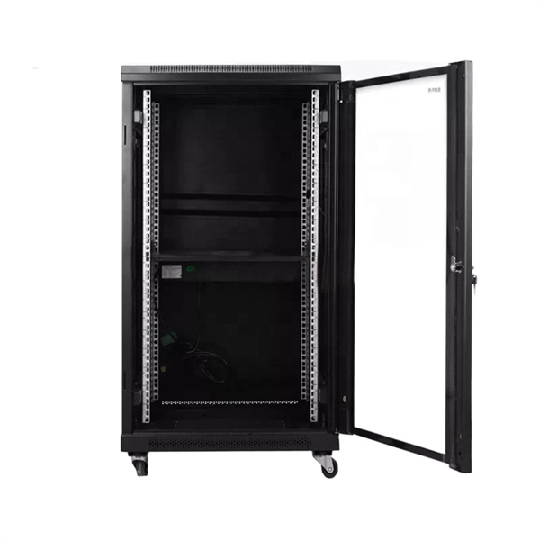
One rack unit equals 1. 45 mm), defined by the EIA-310. Measure your deepest server and add 3–6 inches for cabling and airflow. While rack height is standardized in rack units (U), external dimensions vary by manufacturer. A rack space calculator is a specialized tool designed to help data center professionals, IT administrators, and network engineers determine the optimal placement and space requirements for equipment in server racks. This calculator helps you plan rack layouts by calculating the total rack units. Server rack height is measured in rack units (U). Use the. When planning LAN infrastructure, selecting the correct data rack size is essential for proper equipment fit, ventilation, cable management, and future expansion. A practical formula often used for estimating the required rack size is: Rack size = 1. Common sizes: 42U, 48U, and compact options like 22U–27U. Standard width is 19 inches (EIA-310 compliant), while outer widths vary (e. Rack depth matters for. The three primary dimensions to consider are rack height (measured in rack units or U), rack width (most commonly the industry-standard 19-inch format), and rack depth (typically ranging from 24 inches to 48 inches). Each of these factors influences equipment fit, airflow management, cable routing.
[PDF]

In Q1 2019 NSS Labs performed an independent test of the Oracle Talari SD-WAN E1000 v7. NSS has created three use cases to represent the most common reasons why enterprises deploy software-defined wide area network (SD-WAN) products: Manageability & Cost, Performance, and Security. The troubleshooting tools are now easily accessible from the various monitoring pages of Cisco SD-WAN Manager, such as Site Topology, Devices, Tunnels, and Applications, thereby providing you with context-based troubleshooting guidance. For information on interface bandwidth, see the Interface Summary Report. This report is available in WatchGuard Cloud for Fireboxes that run Fireware v12. To view the report, you must configure. The Monitoring tab is a dashboard that displays a summary widgets of all your SD-WAN device health metrics. This tool provides actionable intelligence about the activity on your SD-WAN network, by allowing you to quickly identify applications or links experiencing performance issues. The ideal. Certifications, manuals, datasheets, and specifications for hundreds of thousands of electronic devices. Jump directly to brand. be attenuated by at least 30 dB relative to the maximum in-band peak PSD level in 100 kHz. Set the RBW = 100 kHz, VBW = 300 kHz, Detector = peak. Set Sweep time = auto couple, Trace mode = max hold. Use the peak marker function to determine the maximum amplitude level.
[PDF]