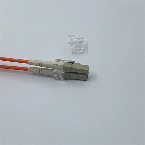
This guide will walk you through the most common fiber connector types, explaining their characteristics, advantages, and typical use cases. An optical fiber connector is a device used to link optical fibers, facilitating the efficient transmission of light signals. An optical fiber connector enables quicker connection and disconnection than splicing. Whether you're planning an FTTH deployment, upgrading a data center, or working in telecom infrastructure, this guide will help you make informed decisions. This guide provides a fully updated and industry-ready overview of LC fiber optics, explaining the origin and design of LC connectors, their key features, and the complete ecosystem of LC-based products used in modern networking. It covers LC connectors, LC patch cables, uniboot designs, armored. Fiber connector types LC, SC, FC, ST, MTP, and MPO are widely used in past and present. What are the differences between them? Who is the most popular one? Find the answer in the article. What is a Fiber Connector? The optical fiber connector is a kind of detachable passive optical component used. The answer often lies in tiny but mighty components called LC connectors. There have been many types of connectors developed for fiber cable. Single mode networks have used FC or SC.
[PDF]
Fiber optic network diagrams represent the architecture and connectivity of fiber optic systems, and their design philosophy integrates technical, functional, and conceptual aspects. The diagrams abstract complex details of fiber optic systems to make them. Fiber optic network design refers to the specialized processes leading to a successful installation and operation of a fiber optic network. It includes first determining the type of communication system (s) which will be carried over the network, the geographic layout (premises, campus, outside. A fiber optics network diagram illustrates how high-speed data travels from an internet service provider to end users. These diagrams help engineers plan infrastructure for residential and commercial buildings. What is fibre network mapping? Fibre network mapping is a critical process in the planning, deployment, and management of fibre optic networks. I'm needing symbols for common fiber optic components, cables, connectors, backbone ports, etc. Can anyone help me out? Some examples of a diagram would also help. 10-27-2018 01:41 AM Do you know if there's some symbol standard. Definition: Fiber optic cable is also called the “ Optical Fiber Cable “, and it is simply Ethernet networking cable that contains the multiple optic fibers, and they allow to transmit data with massive volume. Main goal of designing the optical fiber cable is to offer ultra performance data.
[PDF]
Engineers involved in the design, characterization and validation of Universal Serial Bus Revision 2.0 (USB 2.0) devices face pressure to speed new products to market. Tools are available to help them quickl.
[PDF]

This AutoCAD DWG file includes a complete Single Line Diagram (SLD) of a Distribution Board, showing circuit breakers, wiring connections, and load distribution for lighting, power, and mechanical systems. An electrical panel box, also known as a breaker box or a distribution board, is a crucial component of any electrical system. It serves as a central hub for distributing electricity throughout a building, ensuring that power is delivered safely and efficiently to all the required locations. Whether you're an electrician or a DIY enthusiast, this guide will help you understand the basics of home electrical distribution. What is Distribution Board? Distribution board. Welcome to our channel @Electricalgenius In this video, we'll take you through a detailed step-by-step guide on wiring a home distribution DB (Distribution Board) box. A distribution board (also known as a service panel or breaker box) is a centralized collection of circuit breakers, fuses, and/or relays used to control and protect the wiring in a home. The diagram. To understand how a breaker box works, it is helpful to have a wiring diagram that shows the connections between the various components. At the heart of a breaker box is the main breaker, which controls the flow of electricity from the utility into the building. This breaker is connected to a.
[PDF]
Welcome to our channel! In this video, we'll walk you through the process of wiring a home distribution box with a detailed connection diagram. What is Distribution Board? Distribution board. These smaller breaker panels, also known as sub-distribution boards, are commonly used to provide power to secondary circuits within a building. Understanding the components and wiring configuration of an electrical sub panel is essential for safe and efficient electrical installations. In this. Primary distribution systems consist of feeders that deliver power from distribution substations to distribution transformers. A feeder usually begins with a feeder breaker at the distribution substation. Many feeders leave substation in a concrete ducts and are routed to a nearby pole. This breaker must be compatible with both your main system and the additional connections. Typically, a 60-amp or 100-amp breaker will be suitable, depending on the load requirements. It includes isolator, RCCB (Residual current circuit breaker) or RCD (Residual-current device) devices, protective fuses or MCB's (Miniature Circuit Breaker).
[PDF]

In this guide, you will find a chronological description of the fusion splicing process, the principal technical standards, and answers to the real-life questions network engineers and procurement teams may have. In this guide, we cover the basics of fiber optic splicing, how to perform splicing using two different methods, and finally some best practices to perform good fiber splicing. What is Fiber Optic Splicing and Why is it Needed? – #1. Use and Maintain Your. This Geoschematics drawing remains easy to read despite containing more than 2000 fibers and 500 splices. Splice Diagrams or Matrices capture an electric or optical network inside a location – documenting cables, ported equipment, and connections. Splices are fiber-to-fiber, port-to-fiber and. This guide will walk you through the complete process of fiber optic splicing—covering each step in detail so you can deliver a clean, professional splice every time. Before jumping into the physical steps, it's important to understand the two primary methods of fiber splicing: fusion splicing and. Page 1 The FOSC 450 fiber optic splice closures use compressed-gel cable seals to environmentally seal fiber cable splice points. FOSC 450-ab-c-dd-e-fgh The maximum single splice capacity of the FOSC 450 B6 closure is a = Closure size 144 with 24 splices stored on six trays. Therefore, we will also touch on cost factors, risk management, and best practices in.
[PDF]

This AutoCAD DWG file includes a complete Single Line Diagram (SLD) of a Distribution Board, showing circuit breakers, wiring connections, and load distribution for lighting, power, and mechanical systems. Distribution box The system diagram usually shows the electrical connection and configuration inside the distribution box in a graphical way, including busbars, circuit breakers, fuses, load devices and other elements. In practical applications, the corresponding system diagram can be drawn. An Electrical Distribution Board (DB) is an essential component of any electrical system — it receives power from the Main Distribution Board (MDB) and distributes it to various sub-circuits or equipment. Power supply is received from LT panel and distributed to the outgoing feeders for utilization. Understand its role in electrical systems and safety. Inside. The distribution box (DB box) helps safely and efficiently distribute electrical power. But what exactly is a power distribution box, and why is it so essential in our daily lives? The DB panel board controls the flow of electricity. Wiring diagram shows both PNP and NPN wiring. Actual units use PNP status indicator, NPN status indicator, or neither. Dimensions are shown in mm (in. 40 ft)] or 10 [10 m (32.
[PDF]

Complete pv combiner box wiring diagram guide covering string connections, grounding methods, bonding requirements, and NEC-compliant installation procedures for solar systems. Most wiring diagrams supplied with commercial combiner boxes are simple, easy-to-understand. A clear wiring diagram helps installers understand the flow of current from each string to the main DC bus, making the system safer and easier to maintain. For systems with three or more DC strings, using a solar combiner box is recommended according to international PV safety standards such as IEC. This wiring diagram will guide you in understanding how to properly wire a PV combiner box. One of the key elements of a PV combiner box is the array of fuses or circuit breakers. These safety devices protect the solar panels from overcurrent and short circuits. Understanding proper wiring topology, conductor sizing methodology, and grounding. ing connections,fusing,and grounding. Following the diagram will help ensure the safety,efficiency,and long-term perform nce of your solar panel installat el off the outer shea h of the cable. Check if t is level. Check vertica deviation. Bandage exposed wire. Mea ure. This piece will address the components required for a DC PV combiner box, how to read its wiring diagram and provide a step-by-step tutorial on how to wire it safely and efficiently.
[PDF]
OLX Pakistan offers online local classified ads for Cisco Poe Switch. Post your classified ad for free in various categories like mobiles, tablets, cars, bikes, laptops, electronics, birds, houses, furniture, clothes, dresses for sale in Pakistan. Find the best Cisco Poe Switch in Pakistan. The Cisco DAC-QSFP28-4SFP28-25G breakout cable is a high-performance interconnect solution designed to bridge the gap between 100G core switch ports and 25G server or access switch ports. At SKYRS Pakistan, we provide these high-density cables to optimize data center footprints and significantly. Power Consumption 0. 125W Tested in Targeted Switches for Superior Performance Minimum Bend Radius 60mm for Flexible Routing Supports 100G to 4x 25G Ethernet Interoperability Simplifies Patching and Offers Cost-effective Short Links FS BOX – Support Real-time Configuration Hot Pluggable Cable. In the world of modern networking, Power over Ethernet (PoE) has become an indispensable technology, revolutionizing the way we power and connect devices. PoE network switches play a crucial role in this revolution, offering a streamlined and efficie. POE Network Switch There are 49 products. Pakistan - Shop for Best Online at Daraz. pk Wide Variety of poe switch ip. Great Prices, Even Better Service.
[PDF]

Of the more than a dozen types of fibre-optic connectors available, the four most commonly used today are LC, SC, FC, and ST. Fiber connector types LC, SC, FC, ST, MTP, and MPO are widely used in past and present. What are the differences between them? Who is the most popular one? Find the answer in the article. What is a Fiber Connector? The optical fiber connector is a kind of detachable passive optical component used. Fiber optic connectors are the unsung heroes of modern networking. They are small, often overlooked components, yet they are essential for ensuring high-speed, low-loss, and reliable optical transmission. In addition to serving the same general function, the four connectors differ in size, locking mechanism, and best applications. The following guide systematically describes. Choosing the right connector for an optical link is one of those small decisions that has outsized effects on installation density, reliability, and long-term maintenance. broadband connection is available everywhere. Its. Optical fiber terminations are the mechanical and optical interfaces that connect fiber cables to equipment, patch panels, and network hardware. They directly affect insertion loss, return loss, reliability, and long-term network stability. In this guide, we break down the most common optical fiber.
[PDF]
In this guide, you'll learn how to create rack diagrams that are accurate, scalable, and easy to maintain—so you can plan smarter, troubleshoot faster, and keep your infrastructure organized. This guide will explore the cost breakdown for rack and stack solutions, factors that influence pricing, and how companies can optimize their setup costs for maximum efficiency. Additionally, we will take a closer look at Digital Infotech Solutions, a leader in providing custom rack and stack. Most data center colocation providers hide pricing behind request-for-quote (RFQ) processes. You contact them, wait three to five business days, and only then learn whether colocation fits your budget. This opacity makes it nearly impossible to benchmark costs, negotiate terms, or plan. Whether you're planning a new deployment, reorganizing a rack, or documenting existing infrastructure, a clear visual layout keeps everyone aligned and prevents costly mistakes. Visit our free and simple network rack planning tool to create and export your rack. No registration or download required. Just follow this link and start designing in our pre-designed Server Rack Diagram Template. Before you. A rack diagram is a two-dimensional elevation drawing showing the organization of specific equipment on a rack. It provides a clear overview of the physical layout of the rack, including the placement and positioning of servers, switches, storage devices, and other.
[PDF]
The term host bus adapter (HBA) may be used to refer to a interface card. In this case, it allows devices in a Fibre Channel to communicate data between each other – it may connect a server to a switch or storage device, connect multiple storage systems, or connect multiple servers. Fibre Channel HBAs are available for, computer architectures, and buses, i.
[PDF]
An optical module is a typically hot-pluggable optical transceiver used in high-bandwidth data communications applications. Optical modules typically have an electrical interface on the side that connects to the inside of the system and an optical interface on the side that connects to the outside world through a fiber optic cable. The form factor and electrical interface are often specified by an int. Electrical Interface TypesThere have been multiple variants of the electrical interface of optical modules that have been used over the years. The earliest forms of optical modules had an analog electrical interface. In the transmit dir. Many different forms of optical modulation and multiplexing have been employed in optical modules. The most common modulation technique historically has been or NRZ.
[PDF]