of relay protection coordination for a PV power plant connected to the distribution network is presented. In recent years, installation of PV power plants in the distribution network has increased significantly. I.
[PDF]
The procedures of testing switchgear, instrument transformers and relays are explained in detail. The close and trip, indication and alarm circuits for variety of circuit breakers indicating ferrule numbers are al.
[PDF]
Protective systems in electricity delivery networks have a major role to play in the increasing of renewable energy systems, and a broad understanding of their current a future application can aid into better tak.
[PDF]

Review cutout sizes and modules. See specs, datasheets, order online. Vertical Distribution Managers are available in 8” and 12” widths. The VDM offers quick and easy cable routing for high density cable installation. Optional dual front doors offer easy access to cables and provide an elegant look for your data center. Cable fingers and spools support cables as they. Cable entry frames and kits for enclosures, panels simplify routing and strain relief. 91 inches in height and intended for use with 42U relay racks. It is used to organize cables on a relay rack which helps maintain proper airflow. Forward facing and equipped with a hinged front cover, it makes cable access quick and easy. The manager can also be. The M Series has been specifically designed to meet the demanding & varied requirements for protection relay applications in power utility sub-station environments. The standard 4U high 19-inch rack mounting modular configuration simplifies panel design & installation. Mounting points & overall. Weight capacity: 2,000lb. K04. Rackmount Mart - Rackmount Chassis and Rackmount LCD Source. Provide rackmount chassis, rackmount, rackmount lcd, rackmount monitor, kvm switch, disk array, single board computer, industrial computer, mobile rack, server rack, power supply, server case, raid tower, pc case, accessory, cabinet server.
[PDF]
Distance relays, also known as impedance relay, differ in principle from other forms of protection in that their performance is not governed by the magnitude of the current or voltage in the protected circuit but rather on the ratio of these two quantities.OverviewIn, a protective relay is a device designed to trip a when a is detected. The first protective relays were electromagnetic devices, relying on coils operating on moving par. Electromechanical protective relays operate by either, or. Unlike switching type electromechanical with fixed and usually ill-defined operating voltage thresholds. Electromechanical relays can be classified into several different types as follows: "Armature"-type relays have a pivoted lever supported on a hinge or knife-edge pivot, which carries a moving contact. These relays may.
[PDF]
New relay installations require startup and commissioning to ensure proper protection for your system. Our experience in advanced utility and industrial relay applications includes: 1. General inspection of eq.
[PDF]
It covers standard codes, wiring practices, and norms for protecting generators, transformers, and lines, and provides detailed information on relay characteristics and crycuit design. The department of Electric Power System (EPS) currently has 20 faculty members, including 7 professors (among which Prof. He Jinghan is an IEEE Fellow) and 10 associate professors. In the last five years, the department has undertaken 10 projects funded by the National Natural Science Foundation of. How many people are using ORCID?. The handbook for protection engineers includes guidelines on protective circuitry, protective relay principles, and testing procedures for switchgear and relays. The training program is developed on interchangeable modules that enable to assemble the. ages &importance on Neutral grounding for overall prote s protective schemes for Transformers, Rotating machines, Bus bars, Feeder Restriking Voltage and Recovery voltages - Restriking Phenomenon, Average, Max. RRRV, Current Chopping and Re istance Switching - B ratings and Specifications: Types. The selected protection principle affects the operating speed of the protection, which has a significant im-pact on the harm caused by short circuits. The faster the protection operates, the smaller the resulting ha-zards, damage and the thermal stress will be. Further, the duration of the voltage.
[PDF]

A thermal relay is an electromechanical device that detects temperature changes in electrical circuits, protecting equipment from overload and overheating. Thermal relays are critical components in electrical systems, designed to protect motors and other electrical equipment from damage caused by. So, the thermal relay is one of the types of the relay, used to provide complete safety against single phasing, unbalanced voltages & overloads. Thermal relays are the perfect solution for providing protection to motors which provides the most precise tripping for the electric motor during single. A Thermal Relay is a primary type of circuit breaker that helps protect electrical devices from overheating due to excess current or short circuits. Also known as a thermal overload relay, it operates on the principle of heat generated by. Thermal Relay Definition: A thermal relay is defined as a device that uses the unequal expansion rates of metals in a bimetallic strip to detect overcurrent conditions. Working Principle: The thermal relay operates by heating a bimetallic strip, causing it to bend and close normally open contacts. A thermal relay operates on the principle of the thermal effect of current. It contains a thermal element, often a resistance wire, which generates heat as current flows through it. Most thermal relays use a bimetal strip composed of two metals with different thermal expansion coefficients.
[PDF]

Relay burnout may have been caused by overcurrent, overvoltage, vibration, or short circuit. (It does not mean that the relays burn continuously with flames, because flame-retardant materials are used for the relay components. ) Contact vibration (ultra-frequent switching) causes continuous arcing. Relays burn out for several reasons. Overcurrent is a common cause, where too much current flows through the relay, generating excessive heat. Overvoltage can also damage the relay by applying a voltage higher than it can handle. It requires replacement, but the root cause of the burn-out needs to be identified and resolved first. We mainly use them as they can be used to control much larger levels of power by only using a small level of input power. They also act as an electrical isolation devices as they separate the power circuitry from the. There are several reasons why a relay may fail, including: Excessive current or voltage: A relay may fail if it is exposed to excessive current or voltage, which can burn out the contacts or damage the coil. Mechanical wear and tear: Relays that are used frequently can experience mechanical wear. Relays are basically switches that take up a small control current and use it to administer higher voltage loads. There are varieties of relays and they include General Purpose Relays, Power Relays, Miniature Relays, and PCB Power Relays. In this blog, we review typical failures witnessed with.
[PDF]

A relay protection tester is a core device used to verify the performance of relay protection devices. Its working principle can be summarized as “signal excitation – behavior detection. ”. It is divided into two parts: the main loop and the auxiliary loop. ” The tester has a built-in high-precision programmable power supply, capable of simulating various operating. When the transformer wiring type is Y/Y (Y0), the test wiring is very simple: when testing phase A, the tester IA is connected to the phase A of the high voltage side, and the tester IB is connected to the phase a of the low voltage side. After the neutral line of the high and low voltage sides is. Relay protection aids in detecting and preventing faults in electrical systems such as overcurrents or short circuits. As a core part of electric system reliability and safety, protective relays aid in preserving equipment and maintaining stability by isolating affected zones automatically via. THEY SHOULD BE GIVEN FIRST LINE MAINTENANCE ATTENTION. COMPREHENSIVE INSPECTION, MAINTENANCE AND TESTING PROGRAM. ” relay may only need to operate for 0. 15 seconds in its 30+ year life. But failure to operate as intended can result in extensive damage, extended power outages, and loss of life. NETA. Megger's smart relay testing solutions and expert support help you validate protection performance, improve system reliability, and ensure continuity of power across your network.
[PDF]

The circuit diagram of the protective relay is made up of current transformer primary windings, current transformer secondary windings, relay operating coils, circuit breakers, and the tripping circuit. The relays are in round glass cases. The rectangular devices are test connection blocks, used for testing and isolation of instrument transformer circuits. In electrical engineering, a protective relay is a relay device designed to trip a circuit breaker when a fault is detected. : 4 The first. The working of a protective relay is based on continuous monitoring of electrical quantities such as current, voltage, frequency, and power. A typical protective relay circuit is shown below: Protective Relay Circuit Diagram The first part of the circuit consists of the primary winding of a CT. A relay is a four-terminal electrical switch, used to control any electrical circuit with an independent low-power signal and also to control various electrical circuits with a single signal. The terminals of the relay mainly include; common, coil, NO (normally open) & NC (normally closed). It functions as a watchdog by constantly surveying multiple system components including voltage, current, frequency, and phase angle. During a fault condition, there is a change. Protective relays and devices have been developed over 100 years ago to provide “lastline”of defense for the electrical systems.
[PDF]
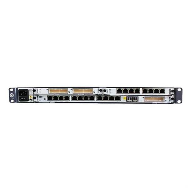
Get Latest Price from the seller Ganesh Electrical - Offering Sifang Relay at Rs 145000 in Gadag, Karnataka. Get Protective Relays at lowest price | ID: 2853527303391. CSC-211 Multifunction Protection IED is selective, reliable and high speed protection IED with rich functions to cover following applications: 1) Protection, bay control unit, MU (Merging Unit), and SCU (Smart control Unit) in one IED; 2) Work as feeder or capacitor bank protection IED; 3) Work as. Copyright © 2020,SIFANG All Right Reserved. Protection relays detect abnormal operating conditions in an industrial system and may trigger an alert or isolate the offending device from the system. The devices can be used for line protection in networks that are grounded, low-resistance grounded, ungrounded, or of a compensated neutral point structure. It is able to supervise. Sifang Relay Install at existing Switch Gear.
[PDF]
The K factor (or zero-sequence compensation factor) adjusts the measured impedance for the phase-to-ground fault loop by accounting for the contribution of zero-sequence currents. This compensation is critical because zero-sequence current introduces an offset in the fault impedance. The protection and control devices in electrical equipment can be referred to by numbers, with appropriate suffix letters when necessary, according to the functions they perform. These numbers are based on a system that is adopted by a standard for automatic switchgear by Institute of Electrical. The following Terms are used in protective relaying: 1. Fault Clearing Time 5. Drop Out or Reset value 8. Sealing Relay or holding Relay 10. Time-graded protection is implemented using overcurrent relays with either definite time characteristic or inverse time characteristic. The operating time of definite time relays does not depend on the magnitude of the fault cur-rent, while the operating time of inverse time relays is shorter the. Displaying title 47, up to date as of 5/06/2026. Title 47 was last amended 4/30/2026. There have been changes in the last two weeks to Part 90. Without proper. Also principles of various protective relays and schemes including special protection schemes like differential, restricted, directional and distance relays are explained with sketches. The norms of protection of generators, transformers, lines and capacitor banks are also given. The procedures of.
[PDF]


