A compilation of available thermal data in Spain, including thermal gradient, heat flow and other thermal indicators, and its interpretation are presented. A regional geothermal gradient map constructed on the basis of data from onshore and offshore oil wells, water wells and geothermal exploration work allows the definition of thermal gradients in the Alpine part of Spain but leaves uncovered the Hercynian part. For this, we have used refined heat producing elements (HPE) values to obtain new estimates of heat production rates in the. Geothermal represented 0. 5 % of the global renewable electricity market in 2022, generating 0. Geothermal energy has a high potential to supply the EU's district heating and cooling sector, while emerging technologies for higher temperatures and efficiency and for. Institute of Earth Sciences (C. Martí i Franquès s/n, 08028 Barcelona, Spain The north-eastern border of the Ebro foreland basin is characterized by relatively high elevation. the presence of Neogene to Present volcanism, and a high thermal gradient. These facts suggest that the area is. The analysis of a 24-year time series of Conductivity-Temperature-Depth (CTD) casts collected in the Balearic Channels (1996–2019) has allowed detecting and quantifying long-term changes in water mass properties in the Western Mediterranean. For the complete period, the intermediate waters have.
[PDF]
Poland's high voltage oil insulated switchgear market is estimated at USD 145–175 million in 2026, with a compound annual growth rate of 3. 5% through 2035, driven primarily by grid modernization and renewable energy integration. Successful go‑live of day-ahead and intraday capacit. informs that under the Single Day-Ahead Marke. Due to changes in information requirements for the electricity market and Polish Power System Operation a new website containing system data has been launched. Transmission substations account for approximately 55–60% of. The electricity transmission network in Poland is managed by Polskie Sieci Elektroenergetyczne SA (PSE), which is the sole transmission system operator (TSO) in the country. The entire power system in Poland and throughout Europe (excluding the frequency of railway electric traction in Germany and. The ANIA Electrical Centre, operating within the structure of ANIA HOLDING, has been providing comprehensive solutions for the distribution of electrical goods for over 30 years. PSE is the owner of Poland's high voltage electricity grid and is responsible for grid. Polenergia Dystrybucja builds and maintains its own power infrastructure across Poland, through which it distributes and sells electricity. Your browser does not support the video tag. Our clients include shopping malls, office buildings, industrial parks, warehouse centers, housing cooperatives.
[PDF]

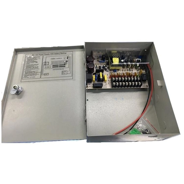
The proper installation of a distribution box involves placing it at the right height to ensure safety and convenience. 7 meters) high makes it easily accessible without the need to bend or stretch excessively. (1) Elevator driving machines, motor generator sets, controllers, and auxiliary control equipment shall be installed in a room or enclosure set aside for that purpose. This height also safeguards the box from potential. The work space shall be clear and extend from the grade, floor or platform to a height of 6 1 / 2 feet or the height of the equipment, whichever is greater. The electrical equipment itself may have a height that is less than 6 1 / 2 feet, but if it is mounted so the top of the equipment is higher. Overcurrent devices and disconnects must be located in machine or control spaces, be lockable and provide a single means to disconnect ungrounded conductors, with selective coordination for multi-elevator feeders. Conductor and wireway fill, approved flexible traveling cables and secure supports. Choose the right box based on environment (indoor/outdoor), load capacity, and durability. Check for proper IP/NEMA ratings and material quality. Ensure safe placement: install in dry, accessible areas with good ventilation and at appropriate height (typically ~1. Practice good wiring: secure.
[PDF]

12KV High Voltage Epoxy Resin Through Wall Bushing for Busbar TG4-12-140x200 , made from high-quality materials with excellent craftsmanship, customisation available. Please contact us for more information. XBRELE's Epoxy Wall Bushings (also known as Through-Wall Insulators) provide reliable electrical isolation for busbars passing through grounded partitions. Featuring TG3 (KYN28) and Gas-Tight (GIS) series, molded via APG technology for zero partial discharge. Designed for high mechanical bending. Our medium voltage through-wall bushings play a critical role in electrical systems by providing reliable separation between busbars and surrounding components. We design these epoxy bushings specifically for medium voltage applications, ensuring they isolate conductors—such as quarter-inch thick. Our bushings for wall applications are specifically designed to be mounted on the wall or tank of electrical power equipment. 5 is a cast epoxy resin combined bushing busbar wall crossing device used in medium and high voltage power equipment. This equipment is usually used in substations and industrial distribution systems to achieve insulation and sealing functions when cables or busbars pass through walls. Description:Wall busing is a type of electrical equipment used to connect high-voltage cables to devices such as circuit breakers and transformers. Resistant to dirt and moisture, the epoxy.
[PDF]

This section provides an overview for busbars as well as their applications and principles. Here are the top-ranked busbar companies as of May, 2026: 1. Chatsworth. Busbars also known as bus bars, barra electrica, or busbar electrical systems are essential components in modern electrical distribution. Whether used in industrial bus bars, EV charging, renewable energy plants, or building infrastructure, busbars offer compact, efficient, and safe current. High Voltage Busbars are critical components in electrical power systems, designed to conduct high voltage electrical currents efficiently and safely. They are used in substations, switchgear assemblies, and electrical distribution systems to connect different parts of the system and manage the. According to Mordor Intelligence, the busbar market was valued at USD 5. 3 billion in 2023 and is projected to reach USD 7. 5% during the forecast period. What. The global busbar market will expand at a great rate and reach USD 19. 24% between 2023 and 2033. The top companies in busbar market are Siemens AG, Connectivity, Mersen, Schneider Electric, Rogers Corporation, Legrand.
[PDF]
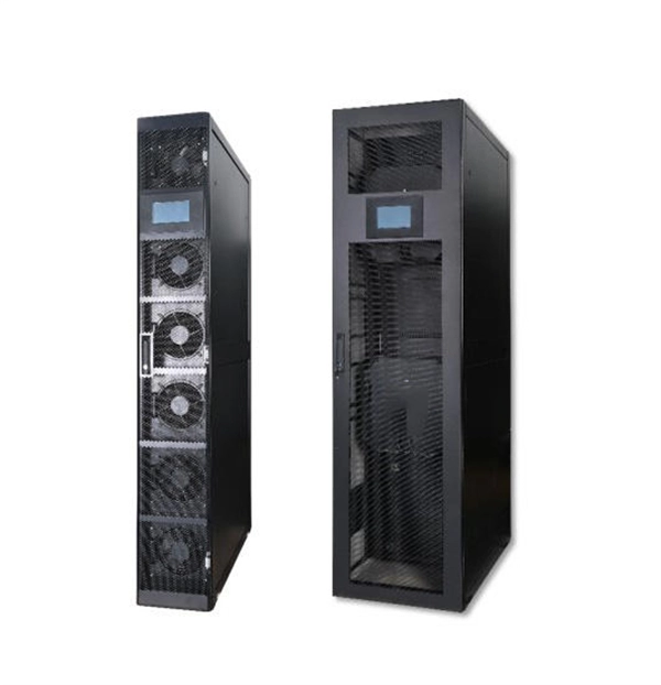
The mounting height of a network rack typically ranges from 24 inches to 84 inches (2 to 7 feet), depending on the equipment and installation requirements. A server rack is more than just a physical frame—it determines how well your rack servers, network switches, PDUs, and storage arrays can be organized, cooled, and maintained. Selecting the right rack size ensures not only compatibility with today's hardware but also room for future expansion. The. Common server rack sizes are 19‑inch width, heights like 42U or 48U, and depths from ~24″ to 48″. Choose size based on equipment type, cooling, space, and future growth. Most IT environments default to 42U, 19-inch width, and 1000–1200 mm depth unless space constraints or special equipment dictate. A rack unit, abbreviated as “U,” is the standard unit of measurement for the height of devices designed for rack mounting. One rack unit equals 1. Important: U describes height only, but a server's real "capabilities" are also determined by chassis depth, internal layout, airflow, rails, power, and expansion (PCIe/risers, NVMe. You'll get precise, vendor-agnostic dimensions for standard server rack sizes—including exact width (19″ internal / 24″ external), height (42U = 73. 5″), depth (24″–48″), and the universal 1U = 1. 75″ rule—plus how to verify usable space, avoid common fitment errors, and select based on equipment.
[PDF]
West Port Middle East specializes in engineering and supplying cable management solutions that meet the precise requirements of electrical contracting projects across the GCC. Unigroup offers a line-up of high-performance cable trays, Trunking and Channel Systems for all your cable routing requirements. Our cable tray systems are engineered for modern infrastructure, ensuring safe, organized, and efficient cable routing across commercial, industrial, and utility. Cable Trays are support systems used in building electrical wiring. These cable support systems are commonly used to support insulated power and communication cables. Cable trays provide a more preferable alternative to electrical conduit systems and open wiring. Cable tray systems are generally. Premium Construction: Made from galvanized steel, stainless steel, or aluminum, these trays resist corrosion and provide high load-bearing capacity in harsh conditions. From residential towers to industrial plants, our extensive portfolio of products and accessories is designed to provide. A form of cable management system used for supporting and arranging electrical cables and wires in commercial, industrial, and residential structures is known as GI Cable Tray, also known as Galvanized Iron Cable Tray.
[PDF]
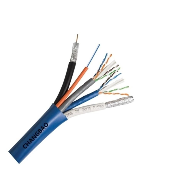
Flex electrical cable, often referred to as flexible cable or flex, is a type of wire that is designed to withstand repetitive bending and movement without damage. Article 400 covers the general requirements and applications for flexible cords as contained in Table 400. A “flexible cord” is two or more insulated conductors enclosed in a flexible covering. Figure 01 The NEC does not. What is a flexible cable? Flexible cables are cables that have multiple conductors (Class 5 or Class 6 conductors) that form the conductor and are insulated and sheathed in a lightweight, flexible material (usually plastic or rubber). Why choose flexible cables for domestic use? It is suitable for. These include flat flexible cable (FFC), stranded wire, power cables, control cables, and flexible electrical conduit. Each type meets specific needs across industries like automotive, electronics, and medical devices. Here is a quick look at how leading cable types are used worldwide: You can. Power distribution cables present a unique challenge to electrical wire interconnect system engineers. Unlike rigid electrical wiring, which is designed for static installations within buildings, walls, or. In any electrical system—whether powering lights in homes, machinery in factories, or robots in operation—cables are the unsung heroes, safely and reliably transmitting electrical energy. As the backbone of power distribution systems, cables connect power sources (such as circuit breakers) to.
[PDF]

Managing optical attenuation helps keep your signal safe. Clean your optical connectors so you do not lose. Optical Signal Attenuation is the single greatest factor limiting the distance and performance of your network. Understanding it is crucial for anyone involved in data centers, telecommunications, or enterprise networking. This guide will demystify signal loss, explore its causes, and show you how. In high-speed environments, where the optical link budget is measured in fractions of a decibel, diagnosing and eliminating unexpected loss is the network engineer's most critical task. This field guide provides a systematic, step-by-step approach to troubleshooting and resolving the most common. Signal loss in Fiber Optic networks can make data slow. It can also break your connection. You should fix it fast to get speed and stability back. > You can solve this with simple steps. Signal Degradation (Loss of Light) When the signal quality degrades, it could be a sign of attenuation or excessive loss in the system. The signal might become weaker, resulting in slower speeds or dropped connections. -. Fiber optic networks are celebrated for their speed and reliability, but even the best systems can encounter problems. When issues like signal loss, slow speeds, or intermittent connectivity arise, systematic troubleshooting is key. Things like impurities in the fiber core and reflections at the core-cladding edge cause this drop.
[PDF]

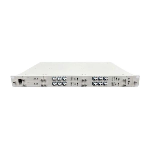
This paper will review the development of fiber-optic high-temperature sensors over the last 30 years, presenting their design and fabrication methods according to sensing type and typical temperature measurement performance. The full paper consists of eight sections. Fiber-optic high-temperature sensors are gradually replacing traditional electronic sensors due to their small size, resistance to electromagnetic interference, remote detection, multiplexing, and distributed measurement advantages. This paper reviews the sensing principle, structural design, and. Luna's Optical Backscatter Reflectometer (OBR) products are based on OFDR and provide a level of detail and precision not available with the prevailing fiber optic diagnostic tool - the optical time domain reflectometer (OTDR). OBR systems map out loss along a single-mode fiber (SMF) or multi-mode. breadth and most comprehensive solutions for optical communications test products to be found in one place. Corning's High Temperature Fibers are designed for applications requiring improved fatigue resistance, high usable strength, and excellent resistance to higher temperatures and hydrogen permeation. Thus, wireless communication -situ processing of data would combined with in significantly improve the ability to include sensors into high temperature systems and thus lead toward more intelligent engine systems. NASA Glenn Research Center (GRC) is presently lea, communication systems,ding the.
[PDF]
In all, there are five steps to manufacture a passive optical splitter. Each step requires strict control and management of various parameters like environment, temperature, and detailed precision on assembly and equipment. We will now provide a detailed introduction using PLC. A fiber optic splitter is a passive optical component that divides a single incoming optical signal into two or more outgoing signals, or combines multiple incoming signals into one. Unlike active devices (which require power), splitters operate without electricity, relying solely on the physics of. The Asia Pacific region (APAC) leads worldwide consumption of Planar Lightwave Circuit (PLC) splitter compact devices with a 68% share, followed by the Americas and the EMEA (Europe, Middle East, and Africa) region. The global PLC Fiber Optic Splitter market was valued at $4. 47 Billion USD in 2020. A fibre optic splitter like 1x2 Fiber Splitter is manufactured in five steps. Step 1: Component Preparation Generally, three components are required. The Evolution of Fiber Splitter Manufacturing Traditional fiber splitter production relied heavily on manual assembly and fused biconical taper (FBT) technology, which struggled to meet modern requirements for uniformity and miniaturization. It can divide the input optical signal into multiple output optical signals to meet the fiber optic access needs of multiple terminal devices.
[PDF]

We show the manufacturing process of DIMI's Fiber Optic Terminal Box / FTTH Termination Box—from raw materials and injection molding to assembly, quality inspection, and packaging. If you're looking for a stable supplier for OEM/ODM and bulk orders, this video helps you un. Our extraordinary customer service, flexibility and skill in managing complex operations in lower cost Southeast Asia has made us the. On June 4, FiberHome Communications' subsidiary Thailand Ruisen Co. (hereinafter referred to as "Ruisen") held a groundbreaking ceremony for its optical fiber and cable manufacturing base. Officials said that the base has a construction area of about 72,000 square meters. The first phase of. Fiber optic termination box is made of ABS and ABS+PC material, which is a box for protecting optical fiber cable and pigtail welding at the termination of the optical cable. As a professional fiber optical terminal box manufacturer, UnitekFiber provides fiber terminal boxes with various waterproof. With the global fiber optic market reaching $6 billion and growing at 10% annually, the need for high-quality manufacturing solutions has never been greater. Single-mode fiber represents the pinnacle of long-distance optical transmission technology. However, the very characteristics that make fiber optic cables.
[PDF]

This video takes you through our highly automated cable tray machine production line. You'll witness how a coil of metal strip is transformed into standardized, ready-to-install cable trays through a series of precision processes. Understanding the intricate world of cable tray manufacturing reveals the sophisticated processes, quality standards, and technical expertise required to produce these essential electrical infrastructure components that power our modern world. The foundation of quality cable tray production begins. HCM-600 Cable Tray Automatic Production Line is a cable tray roll forming line that adopts metal sheet coils as raw material. It forms the sheet into specific shapes and specifications through decoiling, leveling, punching, notching, and roll forming. Together. Producing cable trays involves a detailed and precise process aimed at creating a robust and efficient system for managing electrical cables. These trays are used in various industries for organizing cables that carry power, control signals, or communication lines. Brilltech Engineers Pvt. Ltd is one of the trusted Cable Tray Manufacturers in Chad and brings you the products as per the need of your.
[PDF]