
In this step-by-step tutorial, learn how to splice fiber optic cables like a pro — perfect for telecom technicians, network engineers, and field techs. more 🔧 Watch a real-time fiber optic splicing demo in action!. Fiber cable splicing is a critical step in building reliable fiber optic networks. Whether in data centers, telecom rooms, or outdoor FTTx deployments, proper splicing inside a fiber enclosure ensures low signal loss, long-term stability, and easy maintenance. This guide explains what fiber cable. In this guide, we cover the basics of fiber optic splicing, how to perform splicing using two different methods, and finally some best practices to perform good fiber splicing. What is Fiber Optic Splicing and Why is it Needed? – #1. Whether repairing a broken cable or extending a fiber run, fiber optic splicing ensures light signals travel. Regardless of your level of experience, creating high-quality, high-performance fiber optic networks requires developing your skills in fusion splicing. This guide reveals the secrets to fusion splicing with little fluff—just proven, straightforward techniques refined from years of work in the.
[PDF]
In this report, modeling and experimental results are presented for three fiber Bragg gratings that were fabricated in Newport F-SMF-28 fiber with the direct-write method. The model is based on coupled-mode theory assuming weakly guiding fibers. Optical sensors based on Fiber Bragg Gratings (FBG) are becoming increasingly popular. They are easy to install, immune to electromagnetic interferences and can also be used in highly explosive atmospheres. But just how does a fiber Bragg grating work? Our experts answer this and other questions. One of the particularly useful applications of a direct-write method is for the fabrication of fiber Bragg gratings (FBGs). The. The Bragg grating acts like a mirror which only reflects one very precise wavelength (colour). When the optical fibre is strained or when its temperature changes, the reflected wavelength varies proportionally. Different sensors manufactured using gratings with a specific wave length can be.
[PDF]

The PL-1000D simultaneously monitors up to 16 fiber strands, eight on the OTDR and eight on the OSA, and operates standalone over dark fiber, lighted fiber, or a third party network without impacting network traffic. The device monitors the entire D. The PL-1000D simultaneously monitors up to 16 fiber strands, eight on the OTDR and eight on the OSA, and operates standalone over dark fiber, lighted fiber, or a third party network without impacting network traffic. The device monitors the entire DWDM C-band spectrum and provides the optical spectrum, OSNR, and OTDR measurements of the fiber. The OTDR locates fiber cut by sending high powered optical pulses into the fiber and creating Rayleigh back-reflections. The returning signals are measured and calculated, indicating the accurate location and intensity of the fault. The OTDR supports GIS (Geographic Information System) using Rest API, enabling precise geographic location of disrupt. The OSA enables the user to monitor the OSNR and optical spectrum of each fiber and shows a full, accurate and detailed picture of the wavelengths used in the fiber. OSADiagram Graphical Display of the OSA, from PacketLight's LightWatch NMS Please contact usfor a quote or further assistance.
[PDF]

Shop 100Mbps Network Interface Cards on Newegg. Watch for amazing deals and get great pricing. Any questions? Our AI beta will help you find out quickly. PCIE x8 Interface to Dual 10GbE SFP+ Ports NIC Card, Intel 82599ES 10Gbps Ethernet Controller (X520-DA2) Need help? Discover high-performance fiber optic network interface cards for servers and desktops. Find single and dual port SFP+ adapters with reliable connectivity. Lot Of 45 Router Board RB 433 Free Shipping And Free Tracking!!! Great Price!! Only 1 left! Realtek Fast 200 RTL8139D 10/100M 10/100Mbps. Ethernet Network Lan Card Adapter Only 1 left! Only 1 left! Only 1 left! Only 1 left! Only 1 left! Get the best deals on 100Mbps Internal Network Cards and find. PCI-Express (PCI-E) 1. 0 compliant card installs easily in a PCI-E slot and includes Microsoft® certified drivers. Wake-On-LAN (WOL) power management supported via the PCI BUS. PCI-Express (PCI-E) 1. (Only one port may be in use at a time). This NIC is easily configured for half-duplex or full-duplex operation. Singlemode. Learn why IT Pros trust StarTech.
[PDF]

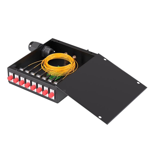
Price and other details may vary based on product size and color. Need help?. This splice enclosure is designed as a simple distribution box for indoor installation. It could be utilised in small building facility or as floor box. Ideal for FTTH networks. This splice enclosure is designed as a. The large single port SC duplex wall outlet serves as a termination point, designed to connect two optical fibers via pigtails in FTTH or FTTB applications. It is small &lightweight, and is typically wall-mounted, providing a convenient sc duplex outlet to connect fiber to an ONT. Internal. Check each product page for other buying options. Need help?. Fiber Optic Splice Enclosures are essential components for protecting fiber optic splices and ensuring safe, secure, and organized fiber management. These enclosures are designed to accommodate splice trays, manage fiber optic cables, and protect sensitive connections from environmental factors. Fiber Optic Splice and Joint Enclosure Box is a fiber management product typically used with outdoor fiber optical cables and underground fiber splice enclosure. Fiber splice enclosure box is used for. CommScope addresses these challenges with a comprehensive family of fiber splice closures that prioritize essential criteria: reliability, installability, flexibility, and speed of deployment. Trunk and Feeder Network Solutions: These closures are designed for robust performance in the backbone of.
[PDF]

In this guide, we'll walk you through the entire process of preparing fiber optic cable for splicing and termination to fiber connectors. We'll explore the necessary tools, safety precautions, and step-by-step procedures for cable connectors, mechanical and fusion. At the heart of any robust fiber optic network lies a crucial process: Preparing a fiber cable for termination of a connector or splice. Two types of splices are used in fiber optic cabling one is Mechanical the other is Fusion. Whether you're installing a new network, expanding an existing one, or. Splicing fiber optic cable is an extremely important phase for making dependable, high-speed communication infrastructures. Regardless of the type of fiber network you're deploying, be it for telecom, enterprise data centers, or smart city infrastructure, fusion splicing provides the benefits of. Think of a fiber optic cable splice as the seamless stitching that keeps data flowing through the delicate threads of a network—like a master tailor joining fabric with precision. This article explains when. We terminate fiber optic cable two ways - with connectors that can mate two fibers to create a temporary joint and/or connect the fiber to a piece of network gear or with splices which create a permanent joint between the two fibers. These terminations must be of the right style, installed in a. So in essence, fiber optic splicing is a process used to join two separate fiber optic cables together.
[PDF]

Fiber optic couplers, also known as fiber optic splitters, are devices used to split or combine optical signals in fiber optic networks. They play a crucial role in various applications, such as telecommunications, data centers, and fiber-to-the-home (FTTH) installations. Whether you're planning an FTTH deployment, upgrading a data center, or working in telecom infrastructure, this guide will help you make informed decisions when choosing fiber connectors. What Are Fiber Connectors? What Are Fiber Connectors? A fiber optic connector is a mechanical device used to. This tab provides a brief explanation of how we determine several key specifications for our 1x2 couplers. In this comprehensive. Fiber optic coupler is one type of fiber optic component that allows for the redistribution of optical signals. A fiber optic coupler is a device that can distribute the optical signal. Fiber optic couplers are a critical element in the landscape of modern telecommunications and data networks. This article explores the function, types, and applications of fiber. Compared to Copper cables, Fiber connector types are incredibly varied. Where copper twisted pairs tend to terminate with an RJ45 plug, fiber optic connectors come in all sorts of shapes and sizes, with all manner of different use cases in mind.
[PDF]
Different networks have different needs when it comes to fiber optic joint closures. At Multilink, we have a variety of closures to meet these needs, including inline types and drop terminals. In our selection, you can find the following termination. Different networks have different needs when it comes to fiber optic joint closures. At Multilink, we have a variety of closures to meet these needs, including inline types and drop terminals. In our selection, you can find the following termination enclosures and splice boxes for use with different cable sizes and numbers of drops: Optima™: The Op. The securing, storing and supporting of fiber optics and splices makes up an important step of fiber optic deployments in the field. Whether connecting to aerial or underground cables, telecommunications companies rely on fiber optic closures to protect and facilitate fiber splices and regular maintenance in Fiber to the Home (FFTH) and other indoo. With more than 35 years of experience, Multilink is a leader in the telecommunications industry. We make innovative products and help our customers succeed by providing high-quality equipment that's laboratory tested and proven to perform. Telecommunications companies often have unique requirements for their equipment. If you have a specific fiber.
[PDF]

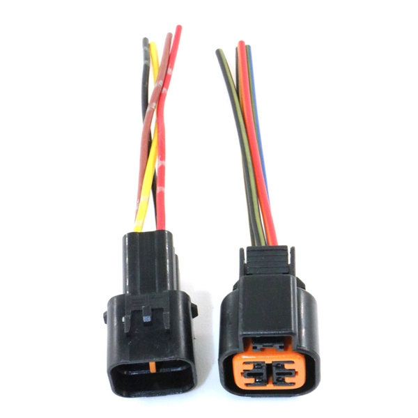
While a cut or damaged fiber optic cable can temporarily take your network down, it is possible to quickly fix the cable with the right tools. This wikiHow article will teach you how to splice a cut fiber optic cable back together with a fiber optic stripper and cutter and a fiber. To connect your fiber optic cable to a router, ensure you have the following: Fiber optic modem (ONT): Most fiber connections require an Optical Network Terminal (ONT), provided by your ISP. Compatible router: Verify that your router supports fiber optic input (look for an SFP or WAN port labeled. The fiber optic cable does not plug directly into a standard home router because the signal type must be translated. The fiber line terminates at the Optical Network Terminal (ONT), which is typically supplied and installed by the internet service provider. This specialized equipment serves as the. The process to connect fiber optic cable to router requires careful attention to detail, but I'll walk you through every critical step with the precision and clarity you deserve. Here's a step-by-step guide to help you through it. Understand the Basics Before diving in, familiarize yourself with the components involved:. See you soon! 🚀 How to connect a fiber optic cable to the router. Check compatibility: Before you begin, make sure your router supports fiber optic connection. Not all routers can connect directly to a fiber cable, so it is important to verify this information before continuing.
[PDF]
This splice case protect fiber optic cables and juction from outside plant environment damage. They are made of reinforced ABS or PC plastic, which has high strength and corrosion resistance. In addition, the splice enclosures are all hermetically sealing structure, waterproof and. Standard polycarbonate (PC) or Glassfibre reinforced (PC+GLAS) PP ABS (Acrylnitrile-butadiene -styrene) Slightly lower UV resistance compared with PC. Recommended for outdoor use if protected against weather influences GRP – GLASS FIBRE REINFORCED POLYESTER Polycarbonate and ABS enclosure materials. The fiber optic splice closure is a closed structure used for splicing, protecting and managing optical fibers. Its material selection is crucial to ensure the quality and service life of the fiber optic splice closure. These boxes are well suited as optical cable splice collection points for DAS (Distributed Antenna Systems), MTU (Multi-Tenant Unit) commercial business applications, and MDU (Multi-Dwelling Unit). It is a reentry box which is made of PC or PP material. The shells and the base are sealed with silicone gum. This product can be re-entered and used again after it is opened. Typically selected for high-density OSP splicing and branching. What is the basic structure of Fiber Optic Splice Closure? The basic structure of Fiber Optic Splice Closure includes the box body, box components, sealing ring, and lock buckle.
[PDF]
Explore verified suppliers offering low-price fiber optic splice boxes, ideal for wholesale. With options from 24 to 144 cores, start your purchase from 1 unit at an average price around $17. TAKFLY COMMUNICATIONS CO. com! Source over 176 fiber-optic splice closures for sale from manufacturers with factory direct prices, high quality & fast shipping. We support our B2B partners with OEM branding, custom configurations, and bulk order discounts, delivering factory-tested solutions for large-scale. COYOTE Closure, 288f/576f ribbon max, Buffer Tube: 8. 5″ x 22″, Includes (1) 3 Section End Plate, (1) Blank End Plate, Organizer, and Lock Tape sealant. FOSC 600 D Dome Closure, 648ct Single/1728ct Ribbon, 8 Ports, Loaded Without Trays, 4 Ground Lugs, 32. 79″, Price Per Ea. ZIP code to view pricing. ZIP code to. Budco is a stocking distribution company for broadband tools, fiber optic tools and cable tools. Since 1970, Budco has provide cable construction tools, cable installation tools, and cable identification tools including fiber optic test equipment and tools for the telecommunications industry. We. This fiber optic splice box is an outdoor fiber optic splice closure used to protect the twisting and joining (splicing) of fiber optic cables. These splice boxes are not made for in-house, off-the-shelf cabling solutions. Instead, they are for installation by professionals laying new fiber optic.
[PDF]

A simple 1-core FTTH drop cable costs around $0. 13 per foot, while a 288-count optical fiber cable for building backbones can reach $6 per foot or more. In this article, we'll take a closer look at the main parameters determining the price of a fiber patch cord, provide up-to-date pricing ranges, and assist you in becoming a smarter buyer—regardless of whether you are making a purchasing decision for a project, replenishing inventory, or placing an. Check each product page for other buying options. Need help?. Fiber-optic cable materials typically cost $1 to $6 per linear foot, depending on fiber count and cable type. Commercial building installations with 100-200 network drops generally range from $15,000 to $30,000. Single-mode fiber costs less per foot than multimode fiber, but it requires more. Knowing how much fiber optic cable costs, which factors can impact cost, and key cost considerations can help you avoid unnecessary expense and get the most out of your budget. First. Get low-loss fiber patch cables & cords with various connector options that support fiber optic cabling up to 400G. Customized cables available. Main cost drivers include cable grade (indoor vs outdoor, armoured), distance, and labor for trenching, splicing, and termination. This guide presents ranges in USD and practical price estimates to help.
[PDF]
Yes, you can connect two routers to one fiber modem, but understanding the 'how' and 'why' is crucial for optimal network performance. This guide clarifies the possibilities, practical methods, and potential pitfalls, ensuring you maximize your home or small office network. Fiber optic technology represents a revolutionary advancement in connectivity, transmitting data via pulses of light through thin strands of glass or plastic fibers. This method enables significantly faster speeds and greater stability compared to traditional copper-based connections. According to. A common solution is to connect two routers on the same fibre optic line. In this article, Axarfusion will guide you through the steps to achieve this configuration and ensure that both routers work in harmony to give you a seamless browsing experience. On each floor each ethernet cable will be connected to a router, which will then distribute the internet. It is indeed feasible to link two routers to one fiber modem and this arrangement can be advantageous, especially in cases of a multi-storeyed residence requiring more WiFi coverage or additional wired connectivity options. But then again, certain guidelines should be followed to run such a. Fiber optic internet delivers blazing-fast speeds and reliable connectivity, making it a top choice for modern homes and businesses. However, setting up a fiber optic connection to your router can seem daunting if you're unfamiliar with the process. Can I Connect Two.
[PDF]
