When Batelco was first founded in 1981, Bahrain already had 45,627 telephone lines in use. By 1982, the number reached 50,000. Batelco enjoyed being a monopoly in the telecommunications sector for the next two. Telecommunications in Bahrain are provided by the Bahrain Telecommunications Company, trading as Batelco, as well as other companies such as Zain and STC. Prior to 1981 telecommunications services were provided by two separate departments: national services were provided by the Bahrain. Explore the evolution of BNET in Bahrain, a testament to the nation's commitment to advancing telecommunications infrastructure and connectivity. BNET won the Gigacity Excellence Award at the WBBA Broadband Excellence Awards 2024! Learn about BNET's evolution and its journey to provide advanced. alth, and to maintaining national competitive advantage. Change in information and telecommunications technology (ICT) has accelerated over the last two ecades, and these two areas have increasingly converged. Since then, other companies such as Zain and VIVA have entered the telecommunications sector. During the same year, Optical fibres and cables were the 479th most exported product (out of 3,333) in Bahrain. In 2024, the main destinations of.
[PDF]

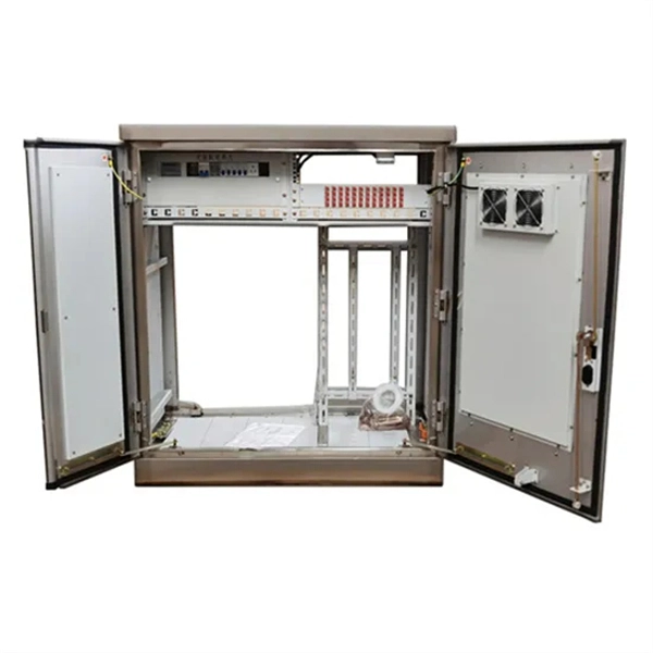
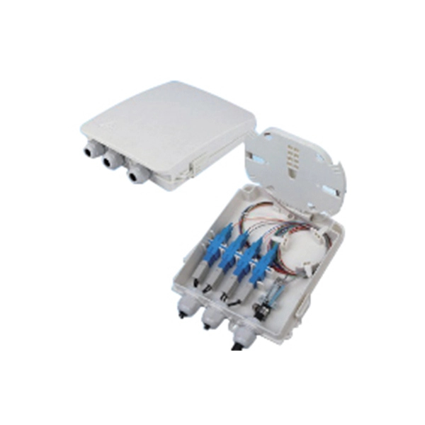
Extending the fiber through the box makes use of a cable entry gland. Fasten the cable to the clamps or ties to assure the cable is immovable. Cable must be properly minimum radius (usually ≥30mm for standard fiber). Remove the cable jacket and buffer coating material. Thus, a fiber termination box is used to terminate the optical fiber cables in the field and connect them to the pigtail by splicing. After an optical cable arrives at the user's end, it is fixed in the terminal box. Fiber adapters: These are used to connect the fiber optic cables to the fiber termination box and should comply with industry. Teleweaver emphasizes the importance of choosing the right FTB based on specific requirements. The common types include: Wall-Mounted FTBs: Ideal for residential and small-scale applications, these are compact boxes designed to be mounted on walls for easy access and space-saving cable management. To address this problem, the fiber termination box (FTB) was created to protect the fragile fiber terminals and provide a simple and clear way to manage the incoming and outgoing cables. more Order it here: https://www. This video shows you a step-by-step instruction on how to terminate 12 strands single mode fiber cables, splicing them with fiber optic pigtails.
[PDF]

Unlike DSL or cable, which use copper wires, fiber optic Internet service relies on optical fiber to transmit data. These fiber optic cables, made of glass or plastic, use light pulses instead of electrical signals, enabling high-speed Internet with low latency and reliable. The process involves a combination of national infrastructure, local engineering, and property-level setup. In this guide, we'll break down the fiber installation process from start to finish and explain key components such as fiber cabinets, flower pods, ducting, and ONT setup. What Is Fiber Optic. Fiber optic internet represents a significant leap forward in broadband technology, offering speeds and reliability far exceeding traditional cable or DSL connections. Check availability first by contacting your internet service provider or visiting their website—fiber now passes over 76 million. The fiber is connected to an Optical Network Terminal (ONT) inside or outside your home. The ONT converts the light from th e fiber into electrical signals that run via an ethernet cable. This fundamental difference is the key to its superior speed, bandwidth, and reliability. The light signals travel at near the speed of light.
[PDF]
from outside the US. EMEA Specific: +49 (0) 228 7489 201 HCS and GiHCS are registered tradema time without notice. This document is for informational purposes only and is not intended to modify or supplement any OFS warranties or specifications relating to any of its. from outside the US. STFOC uses our patented cable jacket construction designed to protect the fiber in the harsh subsea environment. Non-KinkTMSTFOC has a patented design to protect. CommScope bundles hybrid cabling to your custom specifications, using our high-performance fiber-optic, unshielded twisted pair and coaxial cables. Devices deployed at the network edge—a 5G radio, a security camera, or an industrial sensor—require high-speed data connectivity and power. It is technically possible to have a separate fiber and electrical cable, but it adds complexity, cost, and maintenance overhead. Optical hybrid cables address. challenge—OCC has what you need. Our team will make sure the configuration is tailored to your needs and will provide a detailed quote. Email us using the Request a Quote below, or give our team a call. Drive, Avon, CT 0600 erat ing Bend Radiu erat ing Bend Radius Cons from outside the US. Teledyne ODI ofers a comprehensive line of fiber optic and electro/optic hybrid wet mate interconnect products. Wet mate connectors are available in ROV Mate, Stab Mate and Manual Mate configurati sm.
[PDF]

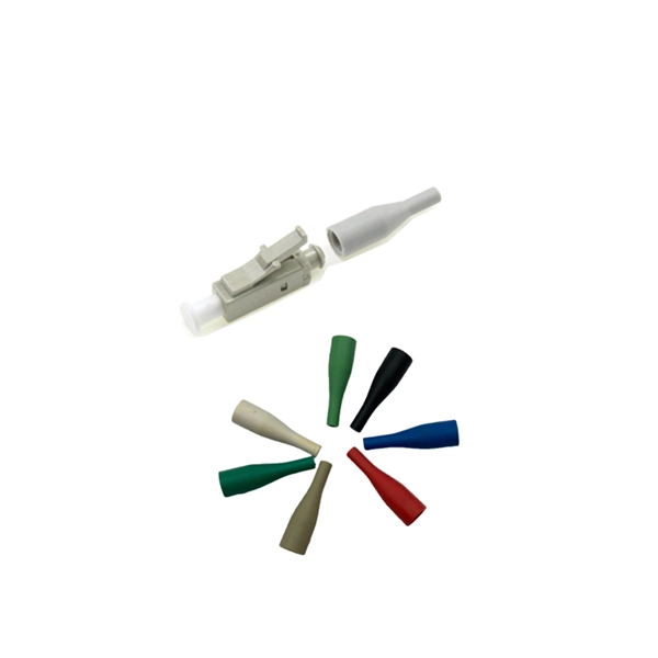
Fiber optic terminal boxes provide functions such as input, branching and splicing of optical fiber cables. Through the connectors and splicing boxes in the terminal box, optical fibers can be quickly connected and repaired. Serving as a critical connection point, FTB facilitates the termination, splicing, or connection of fibers from various cables to other network devices such as switches, routers, or Optical Network Terminals (ONTs). It aids in splicing, splitting, storing, and managing fibers within the appropriate. The optical fiber terminal box is the terminal joint of an optical cable, one end of which is an optical cable, and the other end is a pigtail, which is equivalent to a device that splits an optical cable into a single optical fiber. A fiber pigtail is a specific hardware connection used for cable termination. It is a small enclosure that can house and protect the fiber optic cables, splices, and connectors. The optical fiber termination box and optical fiber splice box serve distinct purposes and are not interchangeable.
[PDF]
The Open Systems Interconnection (OSI) model is a developed by the (ISO) that "provides a common basis for the coordination of standards development for the purpose of systems interconnection." In the OSI reference model, the components of a communication system are disting.
[PDF]

Telescopic mast system with advanced vibration-dampening technology to minimize jitter and ensure stable communication and data transmission, even in the most demanding terrain and vehicle movements. Fireco designs and manufactures the most comprehensive line of standard and custom telescopic masts using high quality materials with industry leading engineering and quality testing practices to provide our customers with the world's best mobile masts. Will-Burt's telescopic masts and tower systems provide intelligent. Telescopic mast systems play a critical role in modern field operations—enabling elevation of cameras, antennas, lights, sensors, and communication gear in demanding environments. Whether for surveillance, broadcasting, defense, or emergency response, choosing the right mast system ensures reliable. Floatograph, along with its utility industry partner, Eversource Energy, developed the Rapid Pole® – Temporary Power Pole system to reduce customer downtime, allowing crews to re-energize a circuit in as little as 20 minutes. Floatograph's masts come in height options from 10 to 100 feet, and are. Advanced telescopic mast solutions designed for versatility in the field, providing crucial support for on-the-move (OTM) missions. Erecting the Telescoping Mast is made by simply connecting guys and brackets to the attached unique heavy duty rolled edge guy rings and clamps, extend the sections, insert the locking cotter pins, rotating the tubes to.
[PDF]

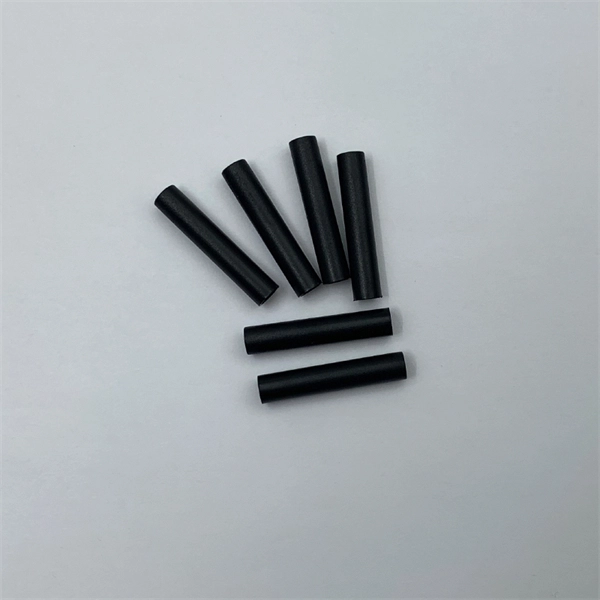
Mainly 9steps: Step 1: cut cable with cutting machines in lengths Step 2: put the connector spare parts on the cable Step 3: Strip cable jacket, coating till bare fiber, and make all parts in ready Step 4: Insert fiber into ferrule, glue dispenser and heat oven Step 5:. Mainly 9steps: Step 1: cut cable with cutting machines in lengths Step 2: put the connector spare parts on the cable Step 3: Strip cable jacket, coating till bare fiber, and make all parts in ready Step 4: Insert fiber into ferrule, glue dispenser and heat oven Step 5:. Learn how to make a fiber optic patch cord step by step, from preparation to testing, for reliable high-performance connections. Most guides on making fiber optic patch cord 1 s feel incomplete. They often focus on the final assembly steps, leaving the foundational stages a mystery. From cable cutting to connector assembly and testing, you will gain valuable insights into the production of. Fiber optic patch cords and Pigtails are very important passive fiber optic components in fiber optic networks. Use the fiber optic cleaver to cut the. This document describes the installation and use of the mode-conditioning patch cords listed in Table 1. A mode-conditioning patch cord is shown in Figure 1 IEEE 802. 3z-compliant optical fiber assembly consisting of a single-mode fiber permanently coupled off-center to a 62. 5-micron multimode.
[PDF]
A fiber-optic cable, also known as an optical-fiber cable, is an assembly similar to an but containing one or more that are used to carry light. The optical fiber elements are typically individually coated with plastic layers and contained in a protective tube suitable for the environment where the cable is used. Different types of cable are used for in different applications, for exa.
[PDF]
Cables 300 V or less need to be a minimum two feet over the street light. NOTE: These values are intended for NESC inspection reference only and are not intended for construction or design criteria. Climbing Space is an unobstructed, vertical space along the side or corner of the. The basic minimum clearances are specified in Tables 1 and 2, Rules 37 and 38 respectively. Modifications are specified in the following provisions: A. Above Ground (1) Over, across or along Public Thoroughfares: Minimum clearance shall not be less than 18 feet (Table 1, Case 3, Column A ). The Fiber Optic Association, Inc. (FOA) was founded in 1995 to help develop the workforce to build the fiber optic networks to support a rapid expansion in communications and the Internet. The charter of the FOA was to promote professionalism in fiber optics through education, certification, and. 40. FO-VC2 JOINT USE - VERICAL MIDSPAN CLEARANCES 48. FO-GB GROUNDING AND BONDING 49. APPENDIX A - COVER SHEET / TOC 52. MunicodeNEXT, the industry's leading search application with over 3,300 codes and growing!. Listed below are illustrative diagrams designed to assist customers with interpretation and calculation of various common regulations or procedural issues. For further clarification, please visit us at the Development Center (first floor of City Hall) or contact us at (408) 535-3555.
[PDF]
There are hybrid optical and electrical cables that are used in wireless outdoor Fiber To The Antenna (FTTA) applications. In these cables, the optical fibers carry information, and the electrical conductors are used to transmit power. These cables can be placed in several environments to serve antennas mounted on poles, towers, and other structures. According to Telcordia GR-3173, Gener. OverviewA fiber-optic cable, also known as an optical-fiber cable, is an assembly similar to an but containing one or more that are used to carry light. The optical fiber elements are typically individually. Optical fiber consists of a and a layer, selected for due to the difference in the between the two. In practical fibers, the cladding is usually coated wit. In September 2012, NTT Japan demonstrated a single fiber cable that was able to transfer 1 per second (10 bits/s) over a distance of 50 kilometers. Although larger cables are available, the highest stra.
[PDF]

The two primary industry-accepted methods for fiber optic cable splicing are fusion splicing and mechanical splicing. The choice between them depends on performance requirements, budget constraints, and the specific application environment. To begin, the standard definition of splicing in optical fiber is joining two fiber optic cables together. Splicing is most commonly used in the field but has application in cable assembly houses. Infield. In this guide, we cover the basics of fiber optic splicing, how to perform splicing using two different methods, and finally some best practices to perform good fiber splicing. What is Fiber Optic Splicing and Why is it Needed? – #1. In this guide, we'll explore what splicing of fiber entails, why it's important, and dive into the key methods and tools. So in essence, fiber optic splicing is a process used to join two separate fiber optic cables together. Through splicing, fiber optic technicians can extend the length of the fiber to make it long enough for use in a required cable run. As. Splicing fiber optic cable is an extremely important phase for making dependable, high-speed communication infrastructures. Termination is the other, more frequent way of linking fibers. Fiber splicing is the preferred way when cable lines are too long for a single length of fiber or when combining two different types of cable.
[PDF]
Long Expansion Cycle: Optical fiber preform production has high technological barriers, and the expansion cycle can take as long as 18-24 months. Even if manufacturers start expanding immediately, the new capacity will not be available until at least 2027. This phenomenon is the result of multiple factors, including tight supply of optical fiber preforms (preforms), long expansion cycles for optical fiber production capacity, and the explosive growth of emerging applications such as AI computing power and drones. The expansion cycle of optical fibers is generally less than 6 months, and fiber optic cables can take 3 months. The expansion of production requires the purchase of equipment and the construction of factories. At the heart of this transformation lies fiber optic cable manufacturing, a precise and sophisticated process that powers our interconnected world. With the global fiber optic market reaching $6 billion and growing at 10% annually, the need for high-quality manufacturing solutions has never been. The manufacturing process of fiber optic cables involves several intricate steps that culminate in the production of high-performance data transmission solutions. This process begins with the creation of a preform, which serves as the foundation for the optical fibers within the cable. This intricate process combines cutting-edge technology, precise engineering, and.
[PDF]