USB keyboards, mice, and I/O devices are the most common devices connected to a KVM switch. The classes of KVM switches discussed below are based on different types of core technologies, which vary in how the KVM switch handles USB I/O devices—including keyboards, mice, touchscreen displays, etc. (USB-HID = USB ) USB Hub Based KVM Also called an Enumerated KVM switch or USB switch selector, a connected/sh.
[PDF]
Engineers involved in the design, characterization and validation of Universal Serial Bus Revision 2.0 (USB 2.0) devices face pressure to speed new products to market. Tools are available to help them quickl.
[PDF]

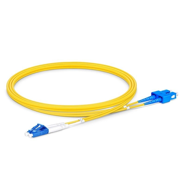
Based on export compliance, verified UL E-files, and consistency in quality control, here are the top 5 Chinese manufacturers producing UL-rated fiber patch cords suitable for enterprise safety in 2025. Before we get to the manufacturers, let's be real about why we are. T&S Communications specializes in a wide range of fiber optic connectivity products, including standard fiber optic patch cords. They offer various types of patch cords, such as simplex, duplex, single-mode, and multi-mode, with different connector options, ensuring high-quality performance for. Fiber optic patch cords are short-distance fiber optic cables used to connect fiber optic equipment. It realizes high-speed and stable data transmission and communication through optical signal transmission. Patch cord has a various application including data centers, network equipment connections. Zhejiang specializes in fiber patch cords and accessories, benefiting from port access for exports. Industrial parks like Wuhan's "Optics Valley" foster R&D partnerships between manufacturers and universities. A “certification” on a. China is home to some of the world's leading fiber optic cable manufacturers, playing a crucial role in global fiber optic communication. As factory-terminated and precisely polished assemblies, they ensure low insertion loss and easy installation. Available in both Singlemode and Multimode configurations, our.
[PDF]

A typical fiber connector (the plug-and-socket type you'd find on patch panels) adds around 0. 5 dB of loss per connection. Higher-quality connectors under ideal conditions can get down to about 0. Attenuation in fiber optics is the gradual loss of light signal strength as it travels through a fiber cable. It's measured in decibels per kilometer (dB/km), and it determines how far a signal can travel before it becomes too weak to read. A standard single-mode fiber operating at 1550 nm loses. Optical Signal Attenuation is the single greatest factor limiting the distance and performance of your network. Understanding it is crucial for anyone involved in data centers, telecommunications, or enterprise networking. This guide will demystify signal loss, explore its causes, and show you how. F iber optic networks rely on the efficient transmission of light signals to deliver high-speed data over long distances. However, various factors can cause signal degradation, leading to performance issues and reduced network reliability. Fiber optic signal loss, also known as attenuation, occurs. Home1 / Blog2 / fiber optic3 / How to Fix High Attenuation & Signal Loss in Fiber Optic Networks. Signal loss in Fiber Optic networks can make data slow. High attenuation makes your system not work well. You may see slower speeds and less steady connections when signal loss goes up. Things like impurities in the fiber core and reflections at the core-cladding edge cause this drop.
[PDF]
Modern fiber-optic communication systems generally include optical transmitters that convert electrical signals into optical signals, optical fiber cables to carry the signal, optical amplifiers, and optical receivers to convert the signal back into an electrical signal. The information transmitted is typically digital information generated by computers or telephone systems. Transmitters The most commo. OverviewFiber-optic communication is a form of for from one place to another by sending pulses of or through an. The light is a form of. First developed in the 1970s, fiber-optics have revolutionized the industry and have played a major role in the advent of the. Because of its advantages over electrical transmission, optical fiber. is used by telecommunications companies to transmit telephone signals, Internet communication and cable television signals. It is also used in other industries, including medical, defense, governmen.
[PDF]
Splicing allows you to restore or expand fiber networks while maintaining signal integrity. When done right, splicing ensures minimal loss and long-lasting performance. This is where fiber optic cable splicing—the process of creating a permanent, high-performance join between two fiber ends—becomes critical. For network managers and technicians, a poor splice can lead to significant signal degradation, network downtime, and costly troubleshooting. At Turn-Key. To begin, the standard definition of splicing in optical fiber is joining two fiber optic cables together. The other, more common, method of joining fibers is called termination or connectorization. Splicing is most commonly used in the field but has application in cable assembly houses. Whether repairing a broken cable or extending a fiber run, fiber optic splicing ensures light signals travel. Whether you're installing new cables or repairing damaged ones, splicing techniques play a vital role in maintaining signal integrity. Choosing the right method affects performance, cost, and long-term durability. In this blog, we'll explore the main types of fiber optic splicing techniques, their. Joining two optical fibers at the right place so that light can be transmitted through them with minimal loss and reflection is known as splicing. Fiber optic splicing is done through two main methods. In fusion splicing, the ends of the fibers are welded together with heat. This guide will walk you.
[PDF]

A differential encoder is often used for bit synchronization. The polarity of the differentially encoded signal can be inverted without having any effect on the decoded signal waveform. A photoelectric signal, output by a photoelectric receiver, may detrimentally change after the photoelectric encoder is used for a period of time or when the environment changes; this will directly affect the accuracy of the encoder and lead to fatal errors in the encoder. To maintain its high. The grating eddy-current of DGECE consists of a circular array of trapezoidal reflection conductors and 16 trapezoidal coils with a special structure to form a differential relationship, which are respectively located on the code plate and the readout plate designed by a printed circuit board. 2 Example showing decoding is the same. This encoder signal error means your A, B, or R channels aren't correctly inverted. Learn how to test your encoder, cabling, and signal integrity. In high-performance control systems using the Siemens SINAMICS drive family, the encoder feedback is crucial. This also changes the direction of the rotation of the constellation changes. In the past I have been told channels. But I have also read that a spectral inversion is equivalent indicate this may be true.
[PDF]


