One of the most common ways to test fiber optic cables is with a light source, which emits light through the cable to detect any potential problems. LED light sources emit. Fiber optic cables are a top choice for high-speed communication systems and can also serve as sensors to measure and monitor various quantities. Modern. Document the end-to-end results for the fiber optic segment you just tested. Related: Data Center Cabling Best Practice Guide Using optical time domain reflectometer testing, you'll measure the length of the fiber optic cable, attenuation, and any events occurring on that fiber segment. Events are. A photodiode is a semiconductor diode sensitive to photon radiation, such as visible light, infrared or ultraviolet radiation, X-rays and gamma rays. It produces an electrical current when it absorbs photons. This can be used for detection and measurement applications, or for the generation of. A typical fiber optic communication system consists of three primary components: a transmitter, a fiber optic cable (the transmission medium), and a receiver. The transmitter usually incorporates a Light Emitting Diode (LED) which converts digital binary data into light waves. The studies cover fiber optic components that have standard SMA connectors to couple with SMA-SMA connectorised PMMA (plas otodiode and a phototransistor. It has a built-in optical power meter an the associated power supplies. Apart from LPS04, the accessories.
[PDF]
The VFL 30mW 30km tester meter is a powerful and versatile instrument capable of tracing and identifying fiber optic cable faults within a range of 30 kilometers. It employs a 30mW VFL light source, which is more than sufficient for long-distance fiber optic testing applications. This QuickTreX ® high quality visual fault locator (VFL) laser test pen is compact, rugged, and perfect for locating bends and breaks in jacketed or bare fiber within 30Km. It's also great for identifying specific connectors in patch panels. This VFL emits red light by using a 650nm semiconductor. Easy to Check Fiber Faults - This visual fault locator can accurately detect and locate fiber breaks, poor connections, bending, or cracking. The detector will emit a 650nm bright light for fiber tracing, breaks or faults in the fiber will refract the light. PRACTICAL DESIGN AND EXCELLENT FUNCTION –. The Pen Shape Visual Fault Locator (VFL) is a robust, cost-effective fiber optical cable test tool for locating faults within OTDR dead zones. As a visual fault identifier (VFI), it can quickly identify faults in fiber optic jumper cables, distribution frames, patch panels, and splice trays. Using. New: A brand-new, unused, unopened, undamaged item in its original packaging (where packaging is. Packaging should be the same as what is found in a retail store, unless the item was.
[PDF]
Cable tray/protective casings are to be assigned with a safe Working Load. The test should be performed according to IEC 60068-2-75:2014 pendulum hammer. (Refer the sketch shown below) The test should be carried out on samples of cable tray lengths or cable ladder. Cable tray load testing ensures your trays can hold the weight without bending or breaking. The bearing capacity is the most basic testing item for the quality of the cable tray. The load-bearing test is also called the SWL (safe working load) test, which is to test the bearing capacity of the cable tray according to the standards of the International Electrotechnical Association. The. Meka Pro measures the safe workload of the cable management systems and corresponding deflection in accordance with the IEC 61537 standard. The safe workload (SWL) is a load [kg/m] that creates a deflection of 1/100 in the span, or if a 1/100 deflection is not achieved, it is the force that creates. This international standard outlines the requirements and tests for cable tray systems used for electrical installations. Whether you're a manufacturer, contractor, or quality assurance engineer, understanding the testing behind IEC 61537 can help ensure your systems meet global safety benchmarks. Samples of ladder should consist of two side-members with one rung positioned centrally. Sa es of the plastics can be maintained for the intended purpose and the installation location. In this particular.
[PDF]

In this article, you will learn the step-by-step process of testing your solar panels using a multimeter. We will cover the essential tools you need, the specific measurements to take, and how to interpret the results. A $15 multimeter and 5 minutes of testing can diagnose most solar panel problems. Measure Voc (open circuit voltage) — if it reads 0V, the panel or wiring is dead. If it reads 60–80 % of rated, a bypass diode has failed. By the end of this guide, you will be equipped with the knowledge to diagnose. Learning how to test solar panel with multimeter is useful for homeowners, technicians, farmers, and anyone using solar energy systems. A digital multimeter allows you to check voltage, current, continuity, and resistance. Fluke recommends using the Fluke 117 Electrician's Multimeter or Fluke 283 FC CAT III 1500 V Digital Multimeter to test solar modules. Here's how a technician tests solar modules with a multimeter:. A multimeter is an indispensable tool for anyone working with solar panels, allowing for accurate measurements and diagnostics. It empowers users to assess the performance, identify faults, and ensure optimal energy production. Perfect for DIY solar builders, RV owners, o. more Audio tracks for some languages.
[PDF]
An OTDR is a powerful tool that helps technicians and engineers assess the health of fiber optic cables. OTDRs inject high-powered light pulses into the fiber using specialized laser diodes. As these light pul.
[PDF]
This study presents the experimental investigations on heat transfer and airflow in a closed refrigerated display cabinet. Air and product temperatures and air velocity were measured with thermocouples and.
[PDF]

Since our inception in 1992, we have proudly established ourselves as one of Singapore's leading specialists in cable support systems. Our expertise lies in crafting quality metal cable trays, trunkings, and ladders for both commercial and industrial projects. At Foresight Metal Engineering, we. Empowering Infrastructure Excellence: Voltecx, Singapore's Premier Manufacturer of Cable Trunkings, Trays, and Ladders Sets the Standard for Superior Quality and Innovative Solutions! Takaso Industries Singapore is a leading provider of innovative cable management systems, offering high-quality. Cable Tray Size: Match the tray width and depth to your cable bundle requirements. Environment: Choose industrial cable trays with appropriate coatings or materials for corrosive, humid, or high-temperature conditions. Standards Compliance: Look for cable management trays that meet international or. Wanco Perforated Steel Cable Trays are constructed using the highest grade of Electro-Galvanised Sheet Steel for Epoxy Powder coating and high grade hot rolled steel for Hot Dipped Galvanised coating. There are basically 3 types of Cable Trays construction: 1. Standard Type (Straight Flange) 2.
[PDF]

This guide will walk you through the essential steps and best practices for wiring LED modules, with insights from industry-leading models such as the LM Series, SLM Series, LM16 Series, and LM13 Series. WAGO's all-new 2070 Series Through-Board SMD PCB Terminal Blocks provide back-side wiring of LED modules. This new design minimizes on-board LED shadowing and simplifies wiring. 2 to. Watch this video to learn how to set up the Near Module. The Module is a retrofit LED module that can fit most aluminium GU10 housings/frames. Tool required: wire strippers, drilland screw driver and screws 1. Noting metal Box depth, width and face material, choose the suitable spacing and quantity of led module, Carefully choose the acrylic panel, the light-diffusion and permeating of which has great effect on brightness and uniform of. © Copyrights. Control what color your want your LED to be with this RGB LED! On-board resistors make it a breeze to wire up! *This module is part of the KY series of sensors which means that the prints on the board might be mislabelled, do read our notes in the description to understand how to wire it properly. All Rights Reserved Buy LED Modules. element14 Singapore offers fast quotes, same day dispatch, fast delivery, wide inventory, datasheets & technical support.
[PDF]

Discover the best prices and detailed specifications for Fibre Optic Cable Patch, with a total of 241 products. Visit BigGo now to find the cheapest deals, stock recommendations, and historical prices all in one place!. Get low-loss fiber patch cables & cords with various connector options that support fiber optic cabling up to 400G. Customized cables available. Pearlyond Technologies Singapore is an ISO9001 certified fiber optic patch cord cable manufacturer and fiber optic test equipment manufacturer since 2001,We supply OEM fiber optic products to world leading companies, our products include fiber optic patch cord,adapter,fiber optic attenuator. When choosing a fiber optic cable patch cord, it is essential to consider compatibility, performance, and application requirements. We offer fiber optic patch cords from Monoprice and Hubbell Premise Wiring in different connector and jacket types, lengths and modes of operation. These cables come equipped with UL rated optical fiber nonconductive rise (ONFR) and optical fiber nonconductive plenum (ONFP) cable jackets, and are.
[PDF]
Since our inception in 1992, we have proudly established ourselves as one of Singapore's leading specialists in cable support systems. Our expertise lies in crafting quality metal cable trays, trunkings, and ladders for both commercial and industrial projects. At Foresight Metal Engineering, we. Cable trays are a fundamental component of modern cable management systems, designed to safely support and organise electrical cables and wires. Typically constructed from durable metals such as steel, aluminium, or stainless steel, cable trays offer a robust and efficient solution for routing. Wanco Perforated Steel Cable Trays are constructed using the highest grade of Electro-Galvanised Sheet Steel for Epoxy Powder coating and high grade hot rolled steel for Hot Dipped Galvanised coating. There are basically 3 types of Cable Trays construction: 1. Standard Type (Straight Flange) 2. Empowering Infrastructure Excellence: Voltecx, Singapore's Premier Manufacturer of Cable Trunkings, Trays, and Ladders Sets the Standard for Superior Quality and Innovative Solutions! Takaso Industries Singapore is a leading provider of innovative cable management systems, offering high-quality. Explore a wide range of cable trays from Ferrograte, including perforated, ladder, FRP, and wiremesh trays—ideal for efficient cable management systems.
[PDF]

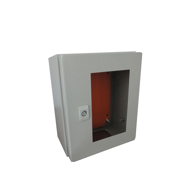
We are a one-stop solution provider of Electrical/ Instrumentation Interface, Enclosures and Hazardous Area Products with reputable and established partner manufacturers in Singapore, France, USA, Germany, India, Finland, Canada & Taiwan. In today's industrial and commercial sectors, reliable Electrical Box Assembly Manufacturer in Singapore solutions are essential for managing electrical systems, ensuring safety, and improving operational efficiency. Our core business is in. Copyright © 2018 AEHUB INTERNATIONAL PTE LTD. All rights reserved Junction Box Enclosure Box. Available in Plastic, Aluminium, Stainless Steel SS304 SS316 Material. Able to Customise as per required Dimension. Sunlink Engineering designs and fabricates high-quality Metal DB Boxes (Distribution Boxes) for safe, organised, and reliable electrical distribution. Our DB boxes are widely used across industrial, commercial, marine, and infrastructure projects in Singapore and Johor, Malaysia, and are engineered. address: NewLight Energy Singapore Pte.,50 Tagore Lane,#05-01i,Enterpreneur Center, Singapore 787494. The XM series distribution box is widely used in building lighting and small power control circuits for power plants, substations, mining enterprises, hotels, apartments, high-rise buildings. Your shopping cart is empty! Your enquiry cart is empty! Copyright © 2026 BSE Electrical Supplies Pte.
[PDF]