In Q1 2019 NSS Labs performed an independent test of the Oracle Talari SD-WAN E1000 v7. NSS has created three use cases to represent the most common reasons why enterprises deploy software-defined wide area network (SD-WAN) products: Manageability & Cost, Performance, and Security. The troubleshooting tools are now easily accessible from the various monitoring pages of Cisco SD-WAN Manager, such as Site Topology, Devices, Tunnels, and Applications, thereby providing you with context-based troubleshooting guidance. For information on interface bandwidth, see the Interface Summary Report. This report is available in WatchGuard Cloud for Fireboxes that run Fireware v12. To view the report, you must configure. The Monitoring tab is a dashboard that displays a summary widgets of all your SD-WAN device health metrics. This tool provides actionable intelligence about the activity on your SD-WAN network, by allowing you to quickly identify applications or links experiencing performance issues. The ideal. Certifications, manuals, datasheets, and specifications for hundreds of thousands of electronic devices. Jump directly to brand. be attenuated by at least 30 dB relative to the maximum in-band peak PSD level in 100 kHz. Set the RBW = 100 kHz, VBW = 300 kHz, Detector = peak. Set Sweep time = auto couple, Trace mode = max hold. Use the peak marker function to determine the maximum amplitude level.
[PDF]
In a news conference today at the University of Chicago, the U. Department of Energy unveiled a report that lays out a blueprint strategy for the development of a national quantum internet, bringing the United States to the forefront of the global quantum race and ushering in a. In a news conference today at the University of Chicago, the U. Exploration and reserves, storage, imports and exports, production, prices, sales. Sales, revenue and prices, power plants, fuel use, stocks, generation, trade, demand & emissions. In the next 20 years, almost three billion people will join the middle class, propelling global demand for more and better housing, televisions, cars, food, water, energy, and myriad other goods and services. But, with increasing strain on the planet's resources, meeting this demand could carry. Husain is director of the FREEDM Systems Center With funding from the National Science Foundation (NSF) leveraged by additional industry support, the Engineering Research Center has sparked the growth of dozens of clean energy businesses in Raleigh's Research Triangle, making the region an. In a news conference today at the University of Chicago, the U. Below are quick statistical highlights providing an overview of the industry. For more detailed information, please see EEI's other resources. 2024 National Energy Resource Mix Coal.
[PDF]
This Report Provides In-Depth Analysis of the U. Fiber-Optic Cable Market Report Prepared by P&S Intelligence, Segmented by Type (Single-mode, Multi-mode, Plastic Optical Fibre), Cable Type (Loose Tube, Tight-Buffered, Ribbon, Armored, Simplex & Duplex Cable), Fiber Type. This Report Provides In-Depth Analysis of the U. The growth of market is attributed to factors such as proliferation of data centres and increasing deployment of 5G network. Increased broadband. The fiber optics industry is projected to reach USD 6. 8 billion by 2029 from USD 3. 4% from 2024 to 2029. Rapid expansion of data centers, cloud services, and 5G infrastructure is driving strong adoption of fiber optic solutions. Rising internet penetration and. Fiber optic cable market has emerged as vital part of the worldwide telecommunications and data transmission system. The fibre optic cables that carry the data by the use of light signals have a much greater advantage over traditional copper cables because they have a higher bandwidth, faster. Fiber optic cables are high velocity information transmission mediums that utilize slight strands of glass or plastic filaments to send data as light signals over significant distances.
[PDF]
Cable tray/protective casings are to be assigned with a safe Working Load. The test should be performed according to IEC 60068-2-75:2014 pendulum hammer. (Refer the sketch shown below) The test should be carried out on samples of cable tray lengths or cable ladder. Cable tray load testing ensures your trays can hold the weight without bending or breaking. The bearing capacity is the most basic testing item for the quality of the cable tray. The load-bearing test is also called the SWL (safe working load) test, which is to test the bearing capacity of the cable tray according to the standards of the International Electrotechnical Association. The. Meka Pro measures the safe workload of the cable management systems and corresponding deflection in accordance with the IEC 61537 standard. The safe workload (SWL) is a load [kg/m] that creates a deflection of 1/100 in the span, or if a 1/100 deflection is not achieved, it is the force that creates. This international standard outlines the requirements and tests for cable tray systems used for electrical installations. Whether you're a manufacturer, contractor, or quality assurance engineer, understanding the testing behind IEC 61537 can help ensure your systems meet global safety benchmarks. Samples of ladder should consist of two side-members with one rung positioned centrally. Sa es of the plastics can be maintained for the intended purpose and the installation location. In this particular.
[PDF]
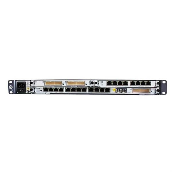
These installation instructions provide overview and specification information for small form-factor pluggable (SFP/ SFP+/SFP28) modules, as well as instructions for installing and removing the modules. SFP (Small Form-factor Pluggable) transceivers are essential components in modern fiber optic networks, enabling network devices such as switches, routers, and servers to transmit and receive data over optical fiber. By converting electrical signals into optical signals—and vice versa—SFP. Gigabit single-mode fiber optic module Common parameters of optical modules 1. Center wavelength 1) 850nm (MM, multi-mode, low cost, but short transmission distance, usually only 500M); 2) 1310nm (SM, single mode, large loss during transmission, small dispersion, generally used for transmission. As a leading provider of fiber optic solutions, Weunion offers a wide range of SFP-compatible products, including optical transceivers, DAC/AOC cables, LC patch cords, and MPO/MTP assemblies. While they may appear to be simple plug-in transceivers, SFP modules are precision-engineered devices that directly influence network. o In optical modules, "core" refers to the light-transmitting channel in the fiber. A 1-core module uses a single fiber core for data transmission, while a 2-core module uses two cores. o Think of a highway. A 1-core fiber is like a single-lane road—only one car (or data signal) can travel at a.
[PDF]

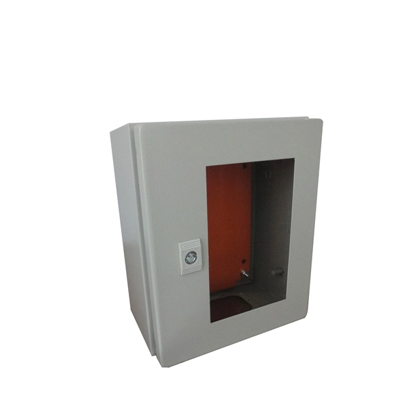
If you use single pole MCBs then connect only phase wire from the output of the RCCB to the inputs of the single pole load MCB. Connect the earth wire to the earth link. A distribution board or distribution box is where the main power supply is distributed to multiple loads. And all the switching and protective devices are installed in the distribution box. Single Phase Distribution Box generally consists of Double Pole MCBs, Single Pole MCBs, and RCCBs. Learn how to wire a distribution box step by step! This video shows real on-site footage of electrical installation, demonstrating safe and standardized wiring methods used by professionals. Arrangement order: The circuit breakers should be arranged from left to right, and the reserved position is generally placed on the right side of the distribution box. Wire color: The neutral wire is blue, and the color of the phase wire (A phase is yellow, B phase is green, and C phase is red). In this video, we'll walk you through the process of wiring a home distribution box with a detailed connection diagram. Whether you're an electrician or a DIY enthusiast, this guide will help you understand the basics of home electrical distribution. What is Distribution Board? Distribution board. An electrical panel box, also known as a breaker box or a distribution board, is a crucial component of any electrical system.
[PDF]
WDM, CWDM and DWDM are based on the same concept of using multiple wavelengths of light on a single fiber but differ in the spacing of the wavelengths, number of channels, and the ability to amplify the multiplexed signals in the optical space.OverviewIn, wavelength-division multiplexing (WDM) is a technology which a number of signals onto a single by using different (i.e., colors) of. A WDM system uses a at the to join the several signals together and a at the to split them apart. With the right type of fiber, it is possible to have a device that does both s. Originally, the term coarse wavelength-division multiplexing (CWDM) was fairly generic and described a number of different channel configurations. In general, the choice of channel spacings and frequency in these co.
[PDF]
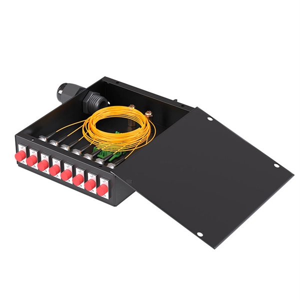
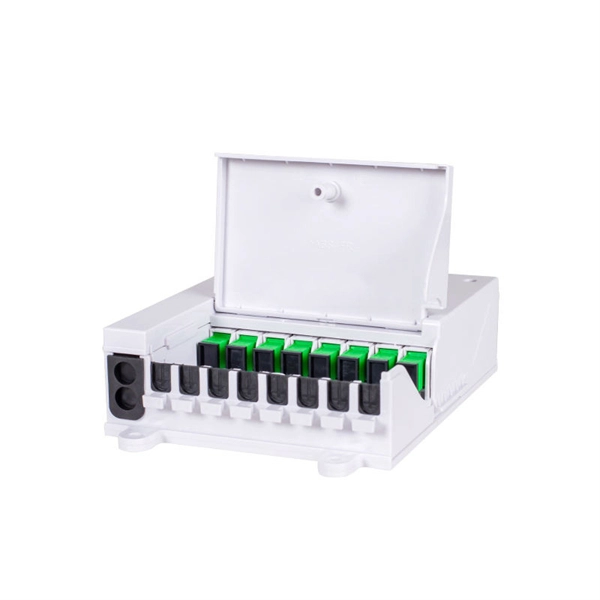
For example, in a FTTH network, a single fiber from the telecom provider can serve 32 homes using a 1:32 splitter, eliminating the need for separate fibers to each residence. These unassuming devices enable a single optical signal to be divided into multiple paths, making them indispensable for sharing network resources efficiently—from residential FTTH (Fiber-to-the-Home) connections to large-scale telecom backbones. This guide demystifies fiber optic splitters. You use optical couplers and splitters to split or join signals in fiber networks. These devices help you control light signals well. For example, optical splitters send light to many output ports. It can divide the input optical signal into multiple output optical signals to meet the fiber optic access needs of multiple terminal devices. This type of device plays an important role in passive. A fiber-optic splitter, also known as a beam splitter, is based on a quartz substrate of an integrated waveguide optical power distribution device, similar to a coaxial cable transmission system. The optical network system uses an optical signal coupled to the branch distribution. The fiber optic. If you've ever wondered how a single fiber from your internet service provider can deliver service to an entire neighborhood or apartment building, you've wondered about the magic of optical splitters. The process of light beam splitting involves.
[PDF]
Single mode and multimode fiber optic cables are two different types of fiber optic cable aimed at different use cases. Single mode cables are typically made with a single strand of glass at their core, leading to a n.
[PDF]
Testing solar panels is easy with a multimeter! To test the current, simply connect the multimeter to the panel's output. Set it to read DC current. To test voltage, set your multimeter to. A $15 multimeter and 5 minutes of testing can diagnose most solar panel problems. Measure Voc (open circuit voltage) — if it reads 0V, the panel or wiring is dead. If it reads 60–80 % of rated, a bypass diode has failed. If Voc is normal but the system is not producing, the problem is downstream. Solar panels are usually tested under standard conditions using a light source that mimics the light from the sun on a clear day. You can use the following method if you want to test your solar panel under standard conditions. We will cover the. A multimeter is a tool that measures the voltage, current, and resistance of an electrical circuit. Fluke recommends using the Fluke 117 Electrician's Multimeter or Fluke 283 FC CAT III 1500 V Digital Multimeter to test solar modules. This helps you spot issues early and keep your system running efficiently. By the end of this guide, you will be equipped with the knowledge to diagnose.
[PDF]
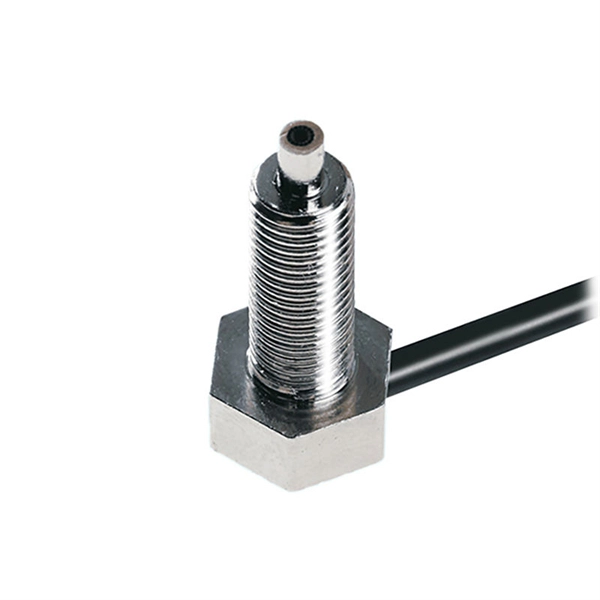
The VFL 30mW 30km tester meter is a powerful and versatile instrument capable of tracing and identifying fiber optic cable faults within a range of 30 kilometers. It employs a 30mW VFL light source, which is more than sufficient for long-distance fiber optic testing applications. This QuickTreX ® high quality visual fault locator (VFL) laser test pen is compact, rugged, and perfect for locating bends and breaks in jacketed or bare fiber within 30Km. It's also great for identifying specific connectors in patch panels. This VFL emits red light by using a 650nm semiconductor. Easy to Check Fiber Faults - This visual fault locator can accurately detect and locate fiber breaks, poor connections, bending, or cracking. The detector will emit a 650nm bright light for fiber tracing, breaks or faults in the fiber will refract the light. PRACTICAL DESIGN AND EXCELLENT FUNCTION –. The Pen Shape Visual Fault Locator (VFL) is a robust, cost-effective fiber optical cable test tool for locating faults within OTDR dead zones. As a visual fault identifier (VFI), it can quickly identify faults in fiber optic jumper cables, distribution frames, patch panels, and splice trays. Using. New: A brand-new, unused, unopened, undamaged item in its original packaging (where packaging is. Packaging should be the same as what is found in a retail store, unless the item was.
[PDF]