
The transmissive liquid crystal spatial light modulator is composed of an active matrix type liquid crystal board of a thin film transistor (TFT) and its accompanying driving circuit. The LCD board is also integrated with some driving circuits, making the driving method more stable. Spatial light modulator (SLM) is a kind of device that can load information on one-dimensional or two-dimensional optical data field, so as to effectively use the proper velocity, parallelism and interconnection ability of light. It is widely used in the field of modern optical information processing. According to the. The LC 2012 is our basic Spatial Light Modulator system based on a translucent liquid crystal microdisplay with a resolution of 1024 x 768 pixel (XGA). The device is mainly intended for proof of concepts and education. Here, we report on the design and realization of an optically addressable. Spatial light modulators, as dynamic flat-panel optical devices, have witnessed rapid development over the past two decades, concomitant with the advancements in micro- and opto-electronic integration technology. The SLMs are available as single mask configuration for phase or amplitude/polarization modulation.
[PDF]

Insertion loss tells you how much weaker the signal becomes after passing through the splitter. Let's say you have a laser output at 0 dBm (which is 1 milliwatt of optical power). If you use a 1×8 splitter with ~10. 5 dB of insertion loss, the power at each output would be: 0 dBm – 10. 5. Enter excess loss from the splitter datasheet for your wavelength. Add connector and splice quantities with realistic planning losses. Include any additional component losses and an engineering margin. Enable power budget to estimate received power and margin. Press Calculate to show results above. Understanding optical splitter loss isn't just about plugging numbers into a calculator. It's about knowing what factors contribute to that loss, how manufacturers specify it, and how it impacts the overall performance and reach of your network. Ignore it, and you might find your signal too weak to. Optical insertion loss refers to the signal loss resulting from the insertion of components such as connectors or splices in an optical fiber system. Common ratios: For cascades, add losses and validate margin using the Optical Budget tool. This Fiber Optic Splitter Insertion Loss is the splitter devices loss, Considering fiber connectors or connectors+adapter insertion loss in LGX, The fiber splitter IL would be a little bigger. To make clear the basic ftth fiber splitter loss in performance, You can refer to the below loss chart.
[PDF]

This SFP module provides 20km transmission distance over single-mode fiber at a nominal wavelength of 1310nm. The transmitter section uses a 1310nm FP laser that is a class 1 laser compliant according to International Safety Standard IEC 60825. A 1310nm optical module lets you move data efficiently through fiber optic communication networks. As part of the O-band (1260–1360 nm), it balances low dispersion, stable performance, and cost efficiency. This makes it widely adopted in data centers, enterprise backbones, and metro access. The transmission distance of optical modules is divided into short distance, medium distance, and long distance. Transmission distances greater than or equal to 30km are considered long-distance transmissions. Light commonly used in optical fiber is 850nm. The GPON OLT SFP transceiver provides an asymmetric 1. 244Gbps upstream and 2. 488Gbps downstream, reaching a link up to 20km over SMF via SC/UPC connector. It can operate at temperatures between -40°C and 85°C. Digital optical monitoring (DOM) support is also present to allow access to real-time.
[PDF]

A laser diode is a semiconductor device that emits light when an electric current is passed through it. The light emitted by it is very intense and narrowly focused, making it an ideal source of light for use in optical fiber communications and laser printers. In this article, we will discuss the. The optical power value, Po, is the most basic characteristic of a laser diode. This parameter is defined as the light output intensity in the case that a specific current is applied to the device in the forward direction, and is typically expressed in units of W. It operates similarly to a light-emitting diode (LED) but produces a focused, monochromatic, and coherent beam of light. These gadgets track down wide applications because of their proficiency and minimal size. When electric current flows through the p-n junction, the gain is. A Laser Diode is a semiconductor device similar to a light-emitting diode (LED). It uses p-n junction to emit coherent light in which all the waves are at the same frequency and phase. They consist of a p-n semiconductor junction, with a forward bias voltage applied.
[PDF]

Specialized Products offers LED and laser fiber optic light sources from AFL, EXFO, VIAVI, Photonix, Tempo Communications and other leading brands. Our selection includes multimode, single mode and quad light sources, with FC, LC, SC, ST connectors and. The state, throughput, and identification of an optical fiber can be easily checked with fiber testers by coupling highly visible laser light into the optical fiber. The red light of a laser is coupled into the core of an optical fiber in a targeted manner (an LED is usually too weak a source to be. Definition: delivery of power for electronic devices via light in an optical fiber which is converted to electricity Alternative terms: power-over-fiber, photonic power Category: fiber optics and waveguides Related: fibers fiber cables laser diodes fiber optics Page views in 12 months: 3730 DOI:. Prizmatix Silver-LED fiber-coupled LEDs provide high power continuous (CW) low noise output as well as fast pulsed operation from optical fiber. Silver-LEDs are available at deep UV, UV, Violet, Blue, Green, Yellow, Red or NIR. Fiber Coupled LED light source modules are ideal for use with high NA. This paper discusses the application of fibre optic technology and its benefits in the operation of solar power plant. Fibre optic technology enhances solar power plant operations, ensuring reliable data transmission and control.
[PDF]
Light sources are devices that generate the optical signals transmitted through fiber optic cables. In fiber communication, the most commonly used light sources are LEDs (Light Emitting Diodes) and laser diodes. LEDs are used in short-distance, low-speed systems due to their broader spectral width. Optical fiber primarily uses infrared light, not visible light, due to lower signal attenuation. Common wavelengths are 1310nm and 1550nm, where silica glass fiber has minimal loss (as low as 0. Lasers or LEDs generate the light, which carries data through total internal reflection within. Most systems use a "transceiver" which includes both transmission and receiver in a single module. The transmitter takes an electrical input and converts it to an optical output from a laser diode or LED. It often uses glass or plastic cables, which address the problems of traditional copper cables' poor speed and limited distance bandwidth carrying. VCSEL (Vertical Cavity Surface Emitting Laser)- VCSELs (pronounced 'vixel') emerged in the 80's as a new kind of semi-conductor laser and were soon recognized for their potential in fiber optics. When Gigabit Ethernet products were developed LEDs could not modulate (turn on and off) at required.
[PDF]

The basic design of an optocoupler consists of a light source, usually an LED (Light-Emitting Diode), driven by the input signal which could be a digital or analogue voltage/current depending upon the characteristics of the light source. An optocoupler (or opto-isolator) is a component that transfer signals between circuits using light. In this guide, you'll learn how they work and how you can use one in your own projects. Optocouplers are very useful when you need to isolate different sections of a circuit, for example in power. Optocouplers, also known as opto-isolators, uses infrared light to transfer electrical signals between two electrically isolated circuits and are commonly classified by their photosensitive output device What is an Optocoupler? An optocoupler (also called an opto-isolator, photo-coupler, or optical. An optocoupler is a tiny part that moves signals between circuits without letting electricity jump across. It uses light to do the job, which helps keep things safe. That way, noisy signals, voltage spikes, or weird grounding issues don't mess with sensitive electronics. Opto-isolators prevent high voltages from affecting the system receiving the signal. We will explore the basics of optocoupler selection and their functionality, helping.
[PDF]
The Lightning Pick system is so intuitive and easy to understand that temporary workers can be effective with just a few minutes of training. Complex systems with steep training curves don't fit modern warehousing and order picking n. The Lightning Pick system is so intuitive and easy to understand that temporary workers can be effective with just a few minutes of training. Complex systems with steep training curves don't fit modern warehousing and order picking needs. Also, these systems are highly adaptable, so they evolve along with your business. Light modules are easy to ad. When an SKU must be picked from a specific location, the right indicator turns on to indicate action is required. The picker selects the quantity displayed and confirms the pick by pressing the lighted button. Light-directed picking systems can easily be configured to drive performance make picking more efficient for: 1. Fast, medium and slow velocity SKUs 2. Order picking, kitting and sortation 3. Full and split-case picking 4. Many popular picking methodologies such as zone picking, cluster picking, bucket brigade, batch picking, order consolidation, s.
[PDF]

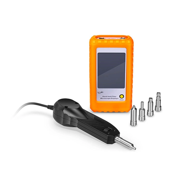
When it comes to testing fiber optic cables, a Visual Fault Locator (VFL) is an essential tool in your toolkit. A VFL is used to detect faults, breaks, or bends in fiber optic cables by emitting a bright red light that is visible even through the fiber's jacket. It's a cost-effective and. A Visual Fault Locator which can be also called visual fault identifier (VFI), fiber fault locator, fiber fault detector, etc., is a visible red laser light designed to inject visible red light energy into an optical fiber. Using a VFL to diagnose issues can save time and cost when diagnosing an. A visual fault locator is a compact, handheld device that emits a visible light beam, typically in the red wavelength range, through a fiber optic cable. It works by injecting a visible red laser light into the fiber, which can be seen through the jacket or at the end of the cable. If the light doesn't come out the other side, there might be a problem. You. And in the end we will show you how to use an old cell phone's camera to detect light in a fiber optic system. It uses a bright incandescent bulb or visible LED source to.
[PDF]

FTTP ONT red light often indicates optical signal loss or fiber cable connection issues. First, check the fiber optic cable for bends, damage, or loose connections at the. An optical audio cable should have a red light at each of the connectors when it's in place and working correctly. If you don't see the light at either of the ends, the cable isn't connected properly, is broken, or you might just have a faulty cable. The light is an indicator of a problem, rather. Customer: The power light is green, the optical light is red, and the UNI-D 1 port is orange. Credit: Jim Gensheimer for Stanford University Light does a lot of work in the modern world, enabling all types of information technology, from TVs to satellites to fiber-optic cables that carry. An optical amplifier is a device which receives some input signal light and generates an output signal with higher optical power. Typically, inputs and outputs are laser beams (very rarely other types of light beams), either propagating as Gaussian beams in free space or in a fiber. The. An optical amplifier is a device that amplifies an optical signal directly, without the need to first convert it to an electrical signal. I'm just wondering because I had a fiber optic cable plugged in and pulled it out while using it and just hoping that didn't cause some issue. Most optical outs are.
[PDF]
S-polarized light is reflected at a 90 degree angle with maximum efficiency of >90%. A beam splitter or beamsplitter is an optical device that splits a beam of light into a transmitted and a reflected beam. It is a crucial part of many optical experimental and measurement systems, such as interferometers, also finding widespread application in fibre optic telecommunications. In its. 📦 For purchasing, use the RP Photonics Buyer's Guide for beam splitters. It provides an expert-curated supplier directory, buyer-focused technical background information, and structured selection criteria to support professional procurement decisions. The beams splitter consists of a pair of precision high tolerance right angle prisms cemented together with a dielectric coating on the hypotenuse. Multi-wavelength beam splitters can be optimised for different ratios of reflected and transmitted light. Thanks to a special coating, the reflectance remains stable for every polarization direction. It is possible to achieve reflectance values of 0. Light from an input fiber is first collimated, then sent through a beam splitting optic to divide it into two. The resultant output beams are then focused back into the output fibers. Both 1XN and 2XN.
[PDF]

Most of the time, restarting your router, checking your cables, or updating the firmware can resolve the blinking red light issue. When it's green and steady, everything is fine. However, when it blinks red or stays solid red, it signifies a Loss of Signal, a problem preventing your router from communicating. That blinking red LOS light means your router has lost its connection to your internet provider's network. Before you panic or call tech support, there are several simple fixes you can try at home that often solve this problem in minutes. The LOS light on your router stands for “Loss of Signal. Normally, each light reflects a specific function: Power Light: Informed if the router is powered on. Wi-Fi Light: Shows the status and. Troubleshoot your router's red light with these steps. It often indicates that something is wrong with your internet connection or the device itself. Fortunately, diagnosing and resolving these issues doesn't have to be. A blinking red light on your router can be frustrating, but don't worry—it's usually a sign of a simple issue that can be fixed quickly. The key is to identify the cause, whether it's a connection problem, firmware glitch, or hardware malfunction. Existing Krishii Fiber customers can share their registered mobile number, area and a.
[PDF]
An optical modulator is a device which is used to a. The beam may be carried over free space, or propagated through an (). Depending on the parameter of a light beam which is manipulated, modulators may be categorized into amplitude modulators, phase modulators, polarization modulators, etc. The easiest way to obtain modulation of intensity of a light beam is to modulate the current driving the light source, e.g. a. This sort of modulation is c.
[PDF]
