
Because fiber optic cables don't come in one continuous length, sections must be joined together through splicing. This process fuses two glass strands so light signals can travel through them without interruption. Below is a detailed look at each step of fiber optic network construction, including key terms and methods used across the industry. Engineers and. We are experts in the installation and use of fiber optic cable to residences, apartment buildings, businesses and cell sites. We complete complex construction projects consisting of aerial and underground deployments in varied, often difficult, working environments. Our services include everything. The Fiber Optic Association, Inc. (FOA) was founded in 1995 to help develop the workforce to build the fiber optic networks to support a rapid expansion in communications and the Internet. Delivers state-of-the-art fiber optics solutions by developing high-tech equipment and subcontractor expertise. Utilizes state-of-the-art technologies to splice a wide variety of different. This recommended practices document is a comprehensive manual for optical fiber construction and testing. Sections are included for project management; cable handling, testing and equipment; overhead cable placement; underground cable placement; underground enclosures; bonding and grounding; cable. 4. FO-VC2 JOINT USE - VERICAL MIDSPAN CLEARANCES 48. FO-GB GROUNDING AND BONDING 49.
[PDF]
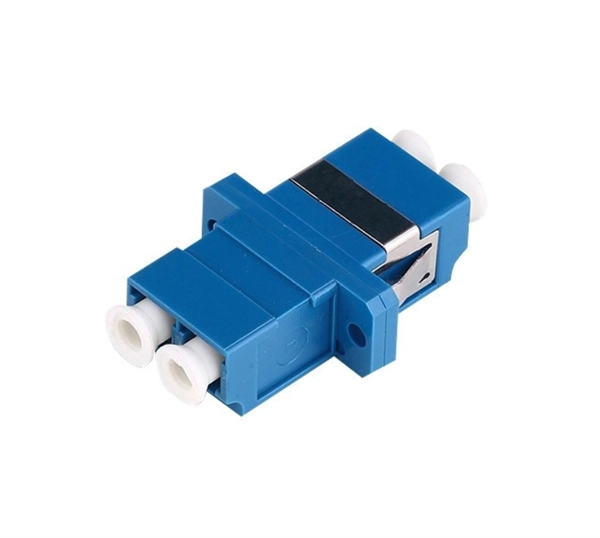
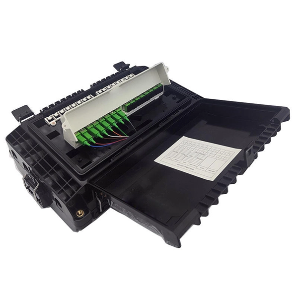
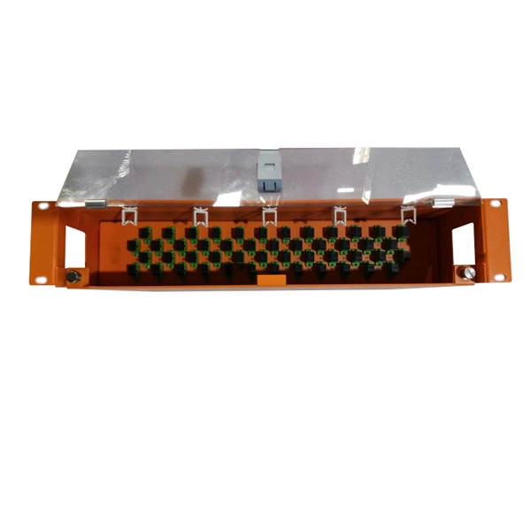
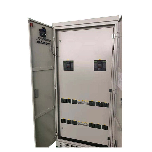
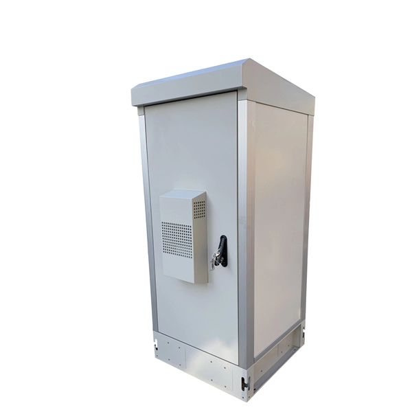
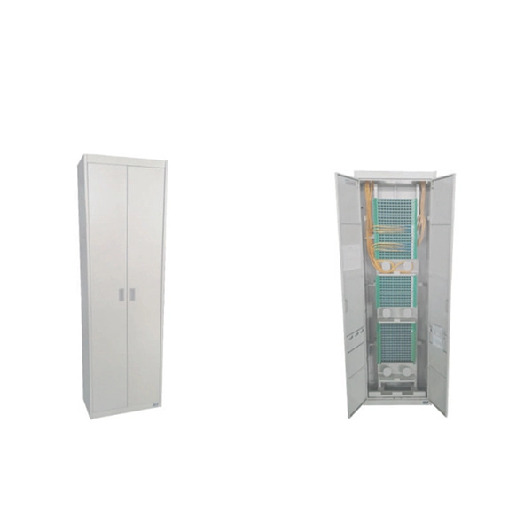
Manufacturers design fiber optic cabinets to protect fiber optic cables in indoor and outdoor environments. Also known as fiber optic enclosures or fiber entrance cabinets, these enclosures act as hubs where ca.
[PDF]
In this guide, you will find a chronological description of the fusion splicing process, the principal technical standards, and answers to the real-life questions network engineers and procurement teams may have. 📦 For purchasing, use the RP Photonics Buyer's Guide for fusion splicers. It provides an expert-curated supplier directory, buyer-focused technical background information, and structured selection criteria to support professional procurement decisions. This article explains the principle of fusion. Fusion splicers play a crucial role in the field of optical fibre communications by enabling the permanent bonding of two strands of glass fibre to create a continuous pathway for light to travel through. This process is achieved through precise alignment and fusion of the fibre ends using an. Fusion splicing is the process of fusing or welding two fibers together usually by an electric arc. Fusion splicing is the most widely used method of splicing as it provides for the lowest loss and least reflectance, as well as providing the strongest and most reliable joint between two fibers. Each splicer is equipped with a cleaver and stripper, conveniently includes in a single case. The goal is to align the microscopic glass cores (typically.
[PDF]

When the heat-shrinkable tube is tightened after splicing, the residual pollutants (such as tiny sand particles) will press the optical fiber and cause the optical fiber to deform, so the splicing loss will increase. At this time, the fiber needs to be cleaned. A fiber optic pigtail is a fiber optic cable with one end terminated with a factory-installed connector and the other end unterminated. As a result, the connector side can be connected to equipment, while the other side is fused in the case of fusion splicing and a mechanical connection in the case. Executive Summary: A fiber optic pigtail is one of the most commonly specified yet least understood components in structured cabling. The guide provides the complete workflow, covering safety precautions, tool selection, fiber preparation, fusion operation, quality control, and. Removes the protective coating to expose the bare fiber for splicing, ensuring no scratches or nicks. Produces a clean, precise fiber end face, critical for low-loss fusion or mechanical splicing. Precisely aligns and fuses fiber ends to form a stable, low-loss connection suitable for long-term. The scientific fiber coiling method can make the optical fiber layout reasonable, the additional loss is small, can withstand the test of time and harsh environment, and can avoid the phenomenon of fiber breakage caused by extrusion. Optic Fiber Management Rules 1. Coil the fibers along the.
[PDF]
It describes three main splicing methods - de-matable connectors, mechanical splices, and fusion splices. Mechanical splices have higher losses than fusion splices. Fusion splicing welds two fibers together using an electric arc and provides the lowest loss. Executive Summary: A fiber optic pigtail is one of the most commonly specified yet least understood components in structured cabling. Get the wrong connector type, the wrong polish, or skip proper fusion splicing technique—and you're looking at elevated signal loss, increased back reflection, and a. Fiber optic cables are the invisible highways of our digital world, carrying massive amounts of data at the speed of light. But what happens when you need to join two cables to extend a network or repair a break? You can't just twist them together. This is where fiber optic cable splicing—the. Fiber Optic Cable is a form of modern network cable that has a far greater capacity than electrical communication connections. Splicing is typically required during cable installation, maintenance, or network expansion. This is essential for extending network reach, repairing breaks, or connecting cables in data centers and telecom infrastructure. The goal is to align the microscopic glass cores (typically.
[PDF]
In this guide, you will find a chronological description of the fusion splicing process, the principal technical standards, and answers to the real-life questions network engineers and procurement teams may have. TMM P021 OPTIC FIBRE CABLE JOINING, TERMINATION & MANAGEMENT Version 9. Therefore, we will also touch on cost factors, risk management, and best practices in. Fusion Splicing • Splicing is the process of connecting two bare fibres directly without any connectors. • Splicing provide much lower insertion loss compared to fiber connectors that's why Splicing is preferred over the use of Connectors. Fiber mechanical splicing – Insertion loss < 0. 5dB Fiber. What is Fiber Optic Splicing and Why is it Needed? – #1. Ensure Your Splicing Tools are Clean – #2. 56 was approved by ITU-T Study Group 6 (2001-2004) under the ITU-T Recommendation A. 8 procedure on 14 May 2003. The International Telecommunication Union (ITU) is the United Nations specialized agency in the field of telecommunications. By following the step-by-step guide provided, you can effectively perform fusion splicing to maintain high-quality fiber optic.
[PDF]
In this comprehensive guide, we delve into the intricacies of fiber optic splicing—encompassing methodologies, instruments, and best practices—while highlighting Dekam Fiber's state-of-the-art offerings that facilitate durable networks. It's the process of joining two fiber optic cables using techniques such as fusion splicing and mechanical splicing, crucial for maintaining uninterrupted communication networks. In this guide, we'll explore what splicing of fiber entails, why it's important, and dive into the key methods and tools. Fiber termination refers to the process of preparing the end of a fiber optic cable to connect to another fiber, a device, or a network. Proper termination is essential for ensuring optimal performance, reducing signal loss, and maintaining the durability of the connection. Unlike using connectors, which are designed for frequent connection and disconnection at patch panels, splicing creates a permanent, stable joint with minimal light loss. What is Fiber Optic Splicing and Why is it Needed? – #1. Use and Maintain Your. Splicing fiber optic cables involves precisely joining two fiber ends to create a continuous optical path. This article explores how to splice fiber, focusing on achieving minimal signal loss and ensuring reliable data transmission through the proper fusion splicing techniques and mechanical.
[PDF]
Fiber optic splicing is the process of joining two fiber optic cables together so that light signals can pass with minimal loss or reflection. Splicing is typically required during cable installation, maintenance, or network expansion. Another method of connecting optical fibers is termination or connectorization, which consists of processing the end of a fiber optic bundle so that it can be connected to other fibers or devices through fiber optic. When deploying fiber optic cabling, one of the most critical decisions is how to terminate the fiber—either by splicing or using connectors. Both techniques have their advantages and are suited for different applications, but understanding which method to use can greatly impact the network's. Fiber optic splicing, crucial for maintaining seamless connectivity in modern communication networks, primarily uses two methods: fusion splicing and mechanical splicing. Fusion splicing provides a low-loss, highly reliable connection by melting and fusing fiber ends, making it ideal for long-haul. As fiber optic connections become increasingly mainstream, the need to connect fiber optic cables to one another — or splicing — is also on the rise. Get the wrong connector type, the wrong polish, or skip proper fusion splicing technique—and you're looking at elevated signal loss, increased back reflection, and a.
[PDF]
Main cost drivers include on-site labor, specialized fusion splicing, testing, and any necessary restoration of network performance. This guide provides practical cost ranges in USD with clear low–average–high estimates to help budgeting and planning. Fiber optic splicing costs vary widely depending on project size, location, fiber type, and site conditions. For most commercial projects, expect to pay $50–$150 per fusion splice point — but that number can swing in either direction based on the factors below. The "per splice" rate is the most. There are two primary methods of splicing fiber optic cables: fusion splicing and mechanical splicing. Each method has distinct characteristics and costs associated with it. Fusion Splicing: This method involves aligning two fiber ends and using an electric arc to melt them together, creating a. Adtell Integration is capable of supporting your fusion splicing requirements whether they require Singlemode, Multimode, or Ribbon Splicing. Fusion Splicing Services: Contractor/Customer Fusion Splicing & Installation Services: Adtell integration offers nationwide fusion splicing services. Specifically fiber used for internet. -W2 employee for a decent size telecommunication contractor, all.
[PDF]

Cable trays are mechanical support systems that provide a rigid structural system for electrical cables, raceways, and insulated conductors used for electric power distribution, control, signal instrumentation, and communication. Cable trays are used as an alternative to open wiring or electrical conduit systems, and are commonly used for cable management in. maintain spacing or to keep cables in place when the tray is ect the minimum bend ra-dius for cables as they exit the bottom of the cable tray. Metal cable trays are made of galvanized steel, stainless steel, and. The modern world relies heavily on electrical and communication cables that must be managed and supported across vast distances in commercial and industrial settings. A cable tray is an organized support structure designed to secure and route these insulated electrical cables. It acts as a. For safe application, observe the following: WARNING To prevent from shock, short-circuits or damage, observe the following: • Be sure the power is disconnected before replacement (fuse exchange, etc. • Use this product in a properly maintained condition. (Replace or repair if the body. What is a cable tray? A cable tray is a metal or non-metal structure used to lay electrical cables and wires, serving to support, protect, and guide the cables. What is the role of a cable tray in electrical engineering? A cable tray allows for the neat and aesthetic arrangement of cables.
[PDF]

Calculate end-to-end loss from cable length, connector and splice counts, and known component losses; verify with a light source + power meter (OLTS). If installed loss exceeds design, reduce connection points, rework poor splices, or use optics with better. This document presents a troubleshooting guide for fiber optic cables once deployed and in regular use. It also includes a list of common fault location items. How to troubleshoot: measure. Fiber optic networks are celebrated for their speed and reliability, but even the best systems can encounter problems. When issues like signal loss, slow speeds, or intermittent connectivity arise, systematic troubleshooting is key. These high-speed, high-capacity communication networks are increasingly replacing copper cables, offering superior performance and. Fiber optic troubleshooting is the systematic process of identifying, diagnosing, and resolving problems within fiber optic communication networks. These networks are the backbone of modern data transmission, offering incredible speeds and bandwidth. However, even the most robust systems can. Fiber optic cables are the backbone of today's high-speed communication networks, powering everything from FTTH broadband to data centers. However, like any technology, fiber optic systems can encounter issues that affect performance. Understanding the common causes and solutions helps maintain.
[PDF]
GYTA is an outdoor stranded loose tube fiber optic cable with aluminum tape armor (indicated by the “A” in GYTA). It is designed for aerial and duct installations but is not recommended for direct burial. It provides an excellent balance of moisture protection and mechanical flexibility, making it the preferred choice for duct and aerial backbone networks. Perfect for long-distance communication. We manufacture high quality products according to European and US standards. The aluminum. Outdoor Duct Optical Cables are strands of specially designed fiber optic cable that are ideally suitable for deployment in underground conduits or ducts. This type of cable guarantees total security for optical fibers while providing long-distance, high-speed data transmission. We supply GYTA fiber optic cable from 2 fiber cores to 288 fiber cores. Both single mode type and multimode types are available. precise control for fiber excess. GYTA fiber optic cable is an outdoor loose tube cable that uses aluminum tape armor for additional mechanical protection. This cable design is commonly installed inside underground ducts or conduits where fiber cables require protection from external pressure and environmental conditions. It is known for its high tensile strength, high flexibility, and excellent transmission performance. In this article, we will discuss the characteristics of the GYTA optical cable.
[PDF]
The Israeli cable trays market is a critical component of the nation's industrial and construction infrastructure, serving as the backbone for organized and secure cable management across diverse sectors. As of the 2026 analysis, the market is characterized by steady demand driven by sustained. A cable tray is an organized support structure designed to secure and route these insulated electrical cables. It acts as a dedicated pathway for power distribution and data transmission, often supporting cables hidden behind walls or above ceilings. People use them in many buildings and work places to give cables a steady place to run. Cable trays come in different types: Materials: They can be metal (like steel with a coating, or stainless steel), plastic (like. In the electrical wiring of buildings, a cable tray system is used to support insulated electrical cables used for power distribution, control, and communication. When properly selected and installed, cable trays simplify routing, improve accessibility, and support future expansion while. Metal cable trays are widely used in demanding industrial settings to support, organize, and protect extensive cabling systems, ensuring efficient and safe power and data distribution. Their robustness and adaptability make them essential in sectors where conditions can be extreme, compliance with.
[PDF]
