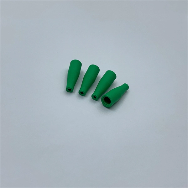
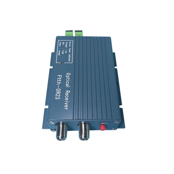
Single fiber modules (BiDi) use one fiber for both transmitting and receiving data. This saves space and money. They are easier to set up and give steady communication. They use a thin fiber. Pioneer LX305 only has 1 optical input, can I add another with some kind of splitter? I love my new receiver but I need a second optical input and I'm wondering what my options are in this regard. Can anyone help? Thanks in advance. Edit: Everyone is going to ask this question, so here are my. The single-mode optical fiber is designed and engineered to carry one single light mode in a minimal core diameter. It is specified as the best for especially long-distance applications than multimode fiber. Due to its. The optical module serves as a crucial component in optical fiber communication systems, operating at the physical layer, which is the lowest layer in the OSI model. Its primary function is to achieve optoelectronic conversion by converting electrical signals into optical signals and vice versa. An. There are single-fiber and dual-fiber optical transceivers. How do we choose, and what are their differences and advantages? Let's learn about this! What is a Single-Fiber (BiDi) Transceiver? Single fiber module also called BiDi transceiver or WDM module.
[PDF]

Mainly 9steps: Step 1: cut cable with cutting machines in lengths Step 2: put the connector spare parts on the cable Step 3: Strip cable jacket, coating till bare fiber, and make all parts in ready Step 4: Insert fiber into ferrule, glue dispenser and heat oven Step 5:. Mainly 9steps: Step 1: cut cable with cutting machines in lengths Step 2: put the connector spare parts on the cable Step 3: Strip cable jacket, coating till bare fiber, and make all parts in ready Step 4: Insert fiber into ferrule, glue dispenser and heat oven Step 5:. Learn how to make a fiber optic patch cord step by step, from preparation to testing, for reliable high-performance connections. Most guides on making fiber optic patch cord 1 s feel incomplete. They often focus on the final assembly steps, leaving the foundational stages a mystery. From cable cutting to connector assembly and testing, you will gain valuable insights into the production of. Fiber optic patch cords and Pigtails are very important passive fiber optic components in fiber optic networks. Use the fiber optic cleaver to cut the. This document describes the installation and use of the mode-conditioning patch cords listed in Table 1. A mode-conditioning patch cord is shown in Figure 1 IEEE 802. 3z-compliant optical fiber assembly consisting of a single-mode fiber permanently coupled off-center to a 62. 5-micron multimode.
[PDF]
It is currently used in modern three-CCD cameras. An optically similar system is used in reverse as a beam-combiner in three- LCD projectors, in which light from three separate monochrome LCD displays is combined into a single full-color image for projection.OverviewA beam splitter or beamsplitter is an that splits a beam of into a transmitted and a reflected beam. It is a crucial part of many optical experimental and measurement systems, such as. In its most common form, a cube, a beam splitter is made from two triangular glass which are glued together at their base using polyester,, or urethane-based adhesives. (Before these synthetic,. Beam splitters are sometimes used to recombine beams of light, as in a. In this case there are two incoming beams, and potentially two outgoing beams. But the amplitudes.
[PDF]

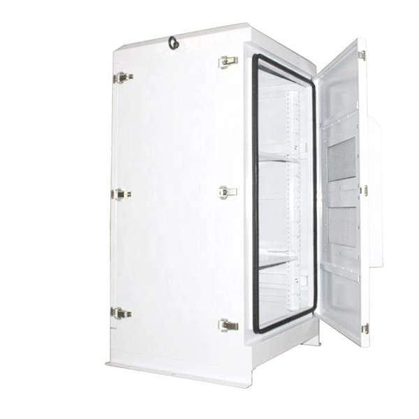
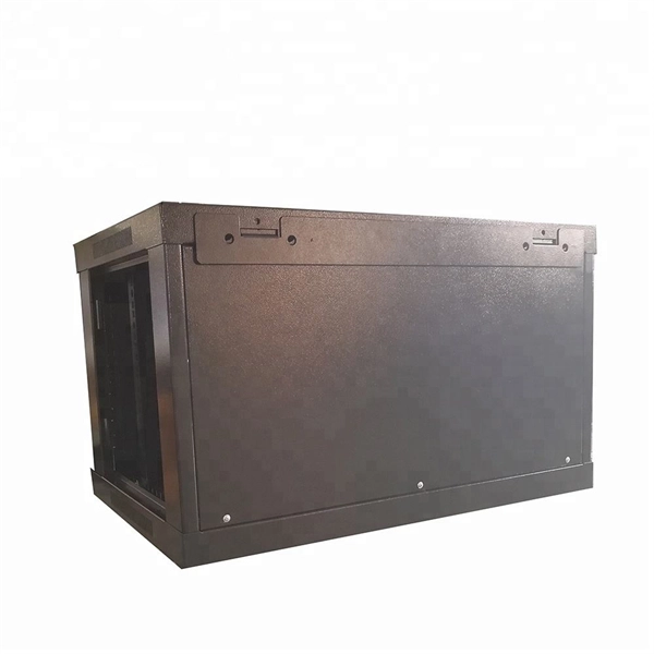
Within data centers, optical distribution boxes manage fiber connections between servers, switches, and storage devices. They enable high-density fiber management, reducing cable clutter and improving airflow. This use-case enhances data transfer speeds and system uptime. They protect delicate fiber cables from environmental factors like moisture, dust, and physical damage. These boxes are used in various settings, including outdoor street cabinets. Optical fiber distribution box (often referred to as optical fiber distribution box or ODF box) plays a crucial role in optical fiber networks, and its advantages are mainly reflected in the following aspects: First, efficient fiber management Modular design: The optical fiber distribution box. These boxes simplify network expansion and reduce installation complexity by combining fiber distribution and signal splitting functions in one enclosure. FDB is used for the purpose of distributing and terminal connection to numerous types of optical fiber systems. They are commonly used by FTTH clients wiring equipment, in order to provide protective connections. The box is compact, light and is widely used for end termination of villas and. An Optical Distribution Frame (ODF) is a specialized enclosure designed to manage, connect, protect, and distribute fiber optic cables in telecom and data networks. It acts as a central point for terminating, splicing, and distributing these cables, providing necessary protection and.
[PDF]
A fiber-optic cable, also known as an optical-fiber cable, is an assembly similar to an but containing one or more that are used to carry light. The optical fiber elements are typically individually coated with plastic layers and contained in a protective tube suitable for the environment where the cable is used. Different types of cable are used for in different applications, for exa.
[PDF]

Abstract-- The zero-sequence relays are widely used to protect radial feeders of distribution network against grounded faults. Positive sequence components represent the ideal operating condition in a balanced three-phase system. Each component: Has equal magnitudes and phase shifts of 120°, rotating counter-clockwise in the same direction as the system's original phasors. a= ej120∘ is a complex operator representing phase. Earth fault protection is critical for detecting ground faults in power systems, protecting personnel, equipment, and ensuring system reliability. Two primary methods are used to detect earth fault currents: Each method has distinct advantages, limitations, and application scenarios. It is widely employed in systems with an ungrounded neutral, a neutral grounded via an arc-suppression coil (Petersen coil), or a. nation in general. Not influenced by load, they contribute to protection speed and sensitivity. However, sequence components are present for a range of conditions, not only faults: open pole, load and line unba ance, breaker pole scatter, and current transformer ratio errors and saturation, to name. To protect the equipment in the electrical power system from ground faults, ground relay protections are installed. Due to the low values of currents during ground faults, residual overvoltage protection is applied as a backup ground protection. because the vectors have the same amplitude and are.
[PDF]
This guide covers the critical steps, from selecting the right electrical cable tray and performing accurate cable fill calculations to managing a safe cable pull through and ensuring all bonding and grounding requirements are met. But before you lay the first tray or clamp down a single cable, you need a solid plan. This guide breaks down the process step by step. Plan the Route Before You Drill No installation should start without a plan. For licensed electricians, mastering these principles is essential. Cable tray installation implies the construction of an electric road that will be safe. In order to get it right, installers are supposed to adhere to a plan that ensures that wires are kept cool and the building is stable. The beginning of success is to review the Bill of Quantities (BOQ) so that. Cable tray systems provide a safe, organized, and flexible method for supporting insulated conductors and cables in commercial and industrial electrical installations. When properly selected and installed, cable trays simplify routing, improve accessibility, and support future expansion while. Proper installation of cables in trays is critical for maintaining an efficient and safe electrical system. This process is integral to determining the optimal arrangement and configuration of cable trays, which are essential for routing and supporting electrical cables within buildings and.
[PDF]

The following are the precautions for the use of Gigabit optical transceivers and 10 Gigabit optical transceivers, some common fault causes, and corresponding troubleshooting methods and solutions. Avoid damage. In the formation of modern networks, optical modules are essential equipment, of which Gigabit optical modules and 10 Gigabit optical modules are popular because of their high speed and stable transmission rate and wide applicability. However, the failure of optical modules is a common problem. 10G SFP+ optical modules remain one of the most widely deployed transceiver solutions in data centers, telecom networks, enterprise switching, and cloud-scale architectures. Their compact size, low power consumption, and versatility across multimode and single-mode fiber make them a critical. Gigabit optical transceivers and 10 Gigabit optical transceivers are an essential part of modern network communication, but they will inevitably encounter some failures during use. This article dives into technical specifications, real-world usage scenarios, selection criteria, and. Single-fiber bidirectional (BIDI) optical modules must be used in pairs. For example, SFP-10G-BXD1 must be used with SFP-10G-BXU1. Cisco XFP Module Main features of the Cisco XFP Module include:.
[PDF]
We determine the noise coefficients of a Fiber Bragg Grating Accelerometer (FBGA) at static operation using Allan Variance Method. We describe the mechanical structure of the FBGA, as well as the embedded optical and electronic circuits used to acquire the experimental data. Fiber Bragg grating (FBG) sensors have emerged as advanced tools for monitoring a wide range of physical parameters in various fields, including structural health, aerospace, biochemical, and environmental applications. This content is available for download via your institution's subscription. To access this item, please sign in to your. Abstract – Fiber optic Bragg gratings have found increasing applications to seismic strain measurement of underground structures and rock mass. The strain sensitivity of a Bragg grating measuring system, however, is limited by the noise caused by the instability of the laser wavelength and the. Fiber Bragg grating (FBG) sensors have proven to be adaptable for monitoring various physical quantitites like temperature, strain, or even vibrations and acoustic noise. Several interrogation methods, like spectroscopic evaluation, interferometric interrogation, active scanning or active filtering.
[PDF]
The STAR Module enables thermal and structural deformation data from FEA packages to be imported directly into OpticStudio where the impact on the performance of your optical system can be analysed. Articles in this section provide guidance on using the Ansys Zemax OpticStudio Enterprise-only feature: STAR. STAR tools allow you to integrate deformation, thermal, and stress effects into your optical design. When you use STAR to import structural FEA data onto a diffractive surface. When constructing fiber-optic transmission lines, the optical cable during the installation and installation process is inevitably subject to external mechanical influences. After completion of construction, especially in regions with significant seasonal temperature fluctuations, residual. Thermo-optical simulation is an important extension of classical ray-tracing because many applications, especially in laser technology, have to deal with thermal effects. This enables a deep understanding of the behaviour of your system. Optical beam deflection is a popular method to measure the deformation of micromechanical devices. We present a method to evaluate precisely these parameters, using the relative amplitude of.
[PDF]
Fiber optic communication relies on transmitting information as pulses of light through thin strands of glass or plastic called optical fibers. Instead of using electrical signals (like in traditional copper wires), it uses electromagnetic radiation in the form of light. This method encodes data into light signals by modulating properties like wavelength, phase, and polarization. The light signals propagate to the receiver through the fiber optic cable. Optical fiber. Okay, let's break down the use of electromagnetic radiation (specifically light) in fiber optic communication. It's a fascinating and crucial technology! Here's a comprehensive explanation, covering the basics, the types of light used, how it works, advantages, and some challenges. The light is a form of carrier wave that is modulated to carry information. This method of data transmission has gained substantial significance in modern communication networks due to its capacity to deliver high-speed internet and other forms of. By using the phenomenon of total internal reflection, light can be transported over long distances without reduction of the energy density due to divergence of the beam. The principle has been known for a long time, but the topic was greatly boosted by the invention of the laser.
[PDF]