
View 18 Communications Equipment Manufacturing company profiles below. There are 88 Telecommunications equipment suppliers in Bolivia as of November, 2025. **** Huawei Technologies. ****. Find detailed information on Communications Equipment Manufacturing companies in Bolivia, including financial statements, sales and marketing contacts, top competitors, and firmographic insights. 06% increase from 2023. 02% of all Telecommunications equipment suppliers in Bolivia are single-owner operations, while the. Market Forecast By Component (Fiber, Transceiver, Switch, Splitters, Circulators), By Technology (SONET/SDH, WDM, CWDM, DWDM, Fiber Channel), By Application (TELECOM, Data Center, Enterprise), By Data Rate (Up To 40 GBPS, Greater Than 40 Gbps To 100 Gbps, Greater Than 100 Gbps), By Vertical (BFSI. Communication Equipment NETWORKS: 1 pc. Seair is proud to have a loyal customer base from big brands. Explore verified Communication importers in Bolivia with customs shipment details, buyers list, and trade data reports for smarter import-export decisions.
[PDF]

Urban Areas: 25–40m spacing (concrete poles, 10–12m height)., steel lattice structures). Factors: Cable weight (kg/km) Ice loading (up to 50mm. The Fiber Optic Association, Inc. (FOA) was founded in 1995 to help develop the workforce to build the fiber optic networks to support a rapid expansion in communications and the Internet. The charter of the FOA was to promote professionalism in fiber optics through education, certification, and. to n utral comm. cable R. FO-CS JOINT USE CLIMBING SPACE REQUIREMENTS 51. APPENDIX A - COVER SHEET / TOC 52. RUS DRAWING #PM12 58. CHECK. d suppliers of electrical construction services. They define a minimum baseline of quality and workmanshi for installing electrical products and systems. NEIS® are intended to be referenced in contrac documents for electrical construction ation or liability to users of this publication. Choose the type of pole The basic pole height is 7m and the tip diameter is 150mm. In case of special sections, crossing obstacles or roads or railways, the pole height of 8m, 9m, etc. can be selected. Cables 300 V or less need to be a minimum two feet over the street light. Climbing Space is an unobstructed, vertical space along the side or corner of the pole. In gen-eral, it consists of an imaginary box, 30-inches square, extending at least 40 inches above the highest communications cable or.
[PDF]

This Code consists of the introduction, definitions, grounding rules, lists of referenced and bibliographic documents, and Parts 1, 2, 3, and 4 of the 2023 Edition of the National Electrical Safety Code. The Institute of Electrical and Electronics Engineers, Inc. 3 Park Avenue, New York, NY. Climbing Space is an unobstructed, vertical space along the side or corner of the pole. In gen-eral, it consists of an imaginary box, 30-inches square, extending at least 40 inches above the highest communications cable or other facility and 40 inches below the lowest communications cable or other. The Fiber Optic Association, Inc. (FOA) was founded in 1995 to help develop the workforce to build the fiber optic networks to support a rapid expansion in communications and the Internet. The charter of the FOA was to promote professionalism in fiber optics through education, certification, and. There are a number of ways of finding out more about cabling standards. You can buy a complete copy of the EIA/TIA or ISO/IEC standards which can be very expensive and wade through page after page of standards language. You can also get catalogs and/or visit the websites of a number of cabling. to n utral comm.
[PDF]
Search by part number or description such as CAT5, CAT6, OSP, etc. Sort by any of the table headers. Use the drop down menu to filter by product category and type. Sort by any. Welcome to the Corning LANscape® Solutions Product Drawings Resource Center, your complete source for our optical hardware component drawings. The two-dimensional and isometric hardware products drawings are available in PDF (Adobe® Acrobat®), DXF (AutoCAD®), VSS (Visio® Stencil) formats, and. Free CAD and BIM blocks library - content for AutoCAD, AutoCAD LT, Revit, Inventor, Fusion 360 and other 2D and 3D CAD applications by Autodesk. CAD blocks and files can be downloaded in the formats DWG, RFA, IPT, F3D. You can exchange useful blocks and symbols with other CAD and BIM users. When possible we have included both linear and nonlinear cable models for your use as appropriate. The use of a linear cable model may be acceptable for calculating loads and sags in an as-built situation such as joint use applications, or when linear elastic behavior and nominal creep are desired. The two linetypes are shown below. The appearance is similar but slightly different. Does anyone have such a code that they could share with me? I struggled for an hour or so and came up with this. There is a small gap on the left side of the circle.
[PDF]

Engineered, manufactured, supported and delivered – with pride. We are a British based manufacturer of Copper Cabling Systems, Fibre Optic Products, Racks and Enclosures – deployed in Datacomms, Data Centres, FTTx & Telecom, Broadcasting and Smart Home Applications. British Cables Company is unique by any standards. Not only have we manufactured cables here in Blackley, Manchester since 1895, but also we are evolving into one of the most proficient service providers in the industry. British and proud? Absolutely! The business has always benefitted from. Alker Fibre Optics is an approved supplier direct to the UK MOD and a trusted partner for a number of specialist prime contractors within the military sector. We are always interested to work. Identify and compare relevant B2B manufacturers, suppliers and retailers Max. The company specializes in cabling and IT infrastructure services, highlighting its expertise in fiber optic cable supply and installation. With over 10 years of experience and a fully accredited team, they ensure. For 25 years Copper & Optic has been providing the highest quality electronic manufacturing services. We produce and supply cable and harness assemblies, PCB and fibre optic assemblies, potting and moulding, and automatic testing. Telecom ducting pipe is a non-flexible PVC pipe that carries telecom & data cables. Products are available for purchase online with free 30 day.
[PDF]
An optical module is a typically hot-pluggable optical transceiver used in high-bandwidth data communications applications. Optical modules typically have an electrical interface on the side that connects to the inside of the system and an optical interface on the side that connects to the outside world through a fiber optic cable. The form factor and electrical interface are often specified by an int. Electrical Interface TypesThere have been multiple variants of the electrical interface of optical modules that have been used over the years. The earliest forms of optical modules had an analog electrical interface. In the transmit dir. Many different forms of optical modulation and multiplexing have been employed in optical modules. The most common modulation technique historically has been or NRZ.
[PDF]

Optical cables are born from ultra-pure glass preforms, drawn into hair-thin fibers, coated for protection, bundled strategically, and encased in durable jackets. This meticulous process ensures light-speed data transmission with minimal loss. Fiber optic cables are the backbone of today's high-speed internet, telecommunication systems, and data transfer technologies. With the increasing demand for faster and more reliable connectivity, the construction of optical fiber cable factories has become essential. In this guide, we will. The Modified Chemical Vapor Deposition (MCVD) process was developed in 1974 at Bell Labs to improve traditional Chemical Vapor Deposition (CVD) methods for fabricating optical fibers. In MCVD, a quartz tube is used as the initial substrate or source material. Fiber optic technology has revolutionized the way information is transmitted, offering numerous advantages over traditional copper wiring. What makes fiber optic cables special is their ability to. Single-mode fiber represents the pinnacle of long-distance optical transmission technology. At Sinoptec, our advanced manufacturing processes ensure each fiber meets rigorous.
[PDF]
In this guide, you will find a chronological description of the fusion splicing process, the principal technical standards, and answers to the real-life questions network engineers and procurement teams may have. TMM P021 OPTIC FIBRE CABLE JOINING, TERMINATION & MANAGEMENT Version 9. Therefore, we will also touch on cost factors, risk management, and best practices in. Fusion Splicing • Splicing is the process of connecting two bare fibres directly without any connectors. • Splicing provide much lower insertion loss compared to fiber connectors that's why Splicing is preferred over the use of Connectors. Fiber mechanical splicing – Insertion loss < 0. 5dB Fiber. What is Fiber Optic Splicing and Why is it Needed? – #1. Ensure Your Splicing Tools are Clean – #2. 56 was approved by ITU-T Study Group 6 (2001-2004) under the ITU-T Recommendation A. 8 procedure on 14 May 2003. The International Telecommunication Union (ITU) is the United Nations specialized agency in the field of telecommunications. By following the step-by-step guide provided, you can effectively perform fusion splicing to maintain high-quality fiber optic.
[PDF]

Definition: Optical Line Terminal or optical line termination is a device that basically acts as a part of a passive optical network (PON). It is present in the central office of the network and manages the transmission and reception of information across the overall network. Optical line terminal. A GEPON system usually consists of an OLT (Optical Line Terminal) at the service provider's central office and multiple ONU (Optical Network Units) or ONT (Optical Network Terminals) close to the end user as optical splitters. In addition, the transmission between OLT and ONU/ONT adopts an optical. An Optical Line Terminal (OLT) is a fundamental element within optical communication networks, serving as a hub that facilitates the transmission and reception of data, voice, and video services to and from subscribers' locations. It acts as the central point for controlling and managing network. In optical fiber technology, one of the most widely used devices is an optical line terminal, also called OLT. It can transmit and receive data at several hundreds of kilometers without loss. The OLT is responsible for converting incoming optical signals into electrical signals, which are.
[PDF]

The solution is to unplug the fiber and reinsert it into the SFP module interface until a “click” sound is heard, indicating the fiber connector and SFP module are properly connected. Contamination or damage on the fiber end face requires the use of a fiber end-face inspection. The physics of noise in optical communication links is of great interest in the design of fiber optic communication systems. The origins of noise in. Optical transceivers—such as SFP, QSFP, and OSFP transceivers —are essential components in high-speed data center and enterprise networks. These fiber optical transceivers convert electrical signals into light and back, enabling long-range, high-bandwidth communication over fiber optic links. Think of it. Optical transmission is vulnerable to various sources of signal degradation, including chromatic dispersion, modal dispersion, polarization mode dispersion, and noise. In the real world, an optical receiver's ability to resolve information is impacted by the presence of noise. They are the foundation of the network world. SFP optical modules are precision devices, and various faults may inevitably occur during operation. These faults can. Noise and Signal Interference in Optical Fiber Transmission Systems is a compendium on specific topics within optical fiber transmission and the optimization process of the system design. It offers comprehensive treatment of noise and intersymbol interference (ISI) components affecting optical.
[PDF]

An SFP port on a gigabit switch works by allowing interchangeable transceiver modules to slot in. These modules convert electrical signals into optical or copper signals, depending on the type you use. You can choose between short-range or long-range, fiber or copper . At Network-Switch. com, we specialize in Cisco-compatible and NS Comm transceivers, offering enterprise customers tested, certified, and globally supported optical solutions. Cisco offers a range of GBIC transceivers and Small Form-factor Pluggables (SFP) transceivers for Gigabit Ethernet and Fibre Channel appications. These small, modular optical interface transceivers offer a convenient and cost effective solution for the adoption of Gigabit Ethernet and Fibre Channel. The SFP port, or Small Form Factor Pluggable in industrial switch is designed for use with SFF (Small Form Factor) connectors and provides high speed and small physical size. With this, it allows to extend the functionality of the device with additional communication standards. The hot-swappable input/output device plugs into a Gigabit Ethernet port or slot. Optical and copper models can be used on a wide variety of Cisco.
[PDF]

Discover APAR Gigavolt hybrid power and fibre cables that cut rollout time, simplify cable management and lower TCO for 5G, IoT and DAS networks. CommScope bundles hybrid cabling to your custom specifications, using our high-performance fiber-optic, unshielded twisted pair and coaxial cables. Buy Direct From The Online Leader in 10-Gigabit Rated Copper and Optical Cables. We always maintain high stocking levels of the. DuetConnect Hybrid Copper-Fiber Cables allow one cable to offer the advantages of DC power and fiber, safely delivering both over long distances to remote locations where standard power is unavailable or too costly to install. These cables integrate fiber optics for high-speed data transfer and copper conductors for power delivery. American Tech Supply is a telecommunications based national stocking distributor of Hybrid Fiber Optic Cables, Hybrid Fiber Cables, Hybrid Singlemode Fiber Optic Cable, Hybrid Multimode Fiber Optic Cable,singlemode fiber optic cable and multimode fiber o ptic cables ranging from 2 fiber to 264 576. Juniper offers a broad portfolio of high-performance and cost-effective optical and electrical cables in various form factors and speeds for data center and campus networks. A wide selection of breakout configurations enables network operators to split out to lower speeds of Ethernet, increase port.
[PDF]

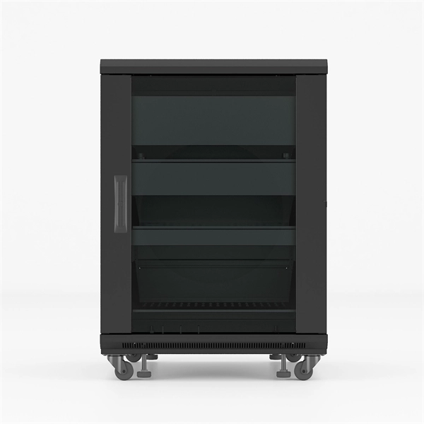
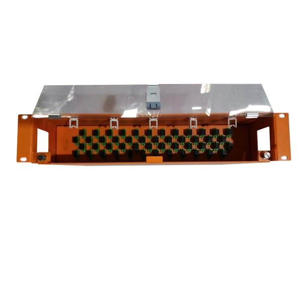
First, connect each pre-terminated fiber optic cable to the adapter panel separately, making sure the ports correspond one-to-one; then fix the fiber optic adapter panel to the front panel of the distribution box with the bend radius control clip. In general, installing the optical fiber distribution box can be divided into three steps: installing the optical fiber distribution box on the rack, introducing the optical cable into the optical fiber distribution box, and planning the optical fiber path in the optical fiber distribution box. The. Bottom installation: Select a proper installation position in the equipment room and drill four holes in the floor according to the dimensions shown in the manual. Fix the rack to the ground with expansion bolts. Top installation: Dimensions of four connection holes on the top according to the. The Optical Distribution Box (ODB) is high-density 2-in-2-out fiber box solution. Designing with a compact size of 340x220x100mm, the cabinet accommodates 1x2,1x4,1x8 and 1x16 etc. The 4 ports are sized for main cable from 9 to 16mm in diameter, along with 16 3mm cables. Accessory Kits:. Install the optical fiber distribution box on the rack. Ensure that the box is installed firmly and horizontally, and the deviation of perpendicularity is not greater than 3mm.
[PDF]
