
This article provides a detailed technical comparison between fiber optic and copper cables, offering a clear perspective for engineers, network architects, and procurement managers. The core distinction between the two technologies lies in the physics of data. However, the exponential growth in data demand has positioned fiber optic technology as the superior alternative for performance, scalability, and future-readiness., 10G/25G/40G/100G and beyond depending on optics and reach). Copper Ethernet scales too, but practical limits are lower and depend. The two main options are fiber optic cables and copper cables, each with its own advantages and drawbacks. Fiber optic cables are praised for their high performance and scalability, while copper cables remain a cost-effective choice, especially for budget-conscious projects and older systems. Copper wire is more susceptible to interference and has limited data capacity, making optical fiber the preferred choice for modern high-speed. Optical connectivity, utilizing fiber-optic technology, has emerged as the superior choice for modern networking, offering unparalleled performance, reliability, and scalability. For example, a typical 10 Gbps copper Ethernet link (such as Cat 6A) over 100 meters can consume approximately 5 to 8+.
[PDF]
The beamsplitter is constructed in a cube shape, with dimensions of 25. 4 mm, providing a robust and stable platform for optical systems. This product is a non-polarizing cube beamsplitter, model 14NBC-25. 4-50/50-700-950, manufactured by Standa. It is designed for use in the 700-950nm wavelength range, making it suitable for a wide range of optical applications. The beamsplitter has a 50:50 reflection to transmission ratio, meaning. 【Professional Teleprompter Glass】NEEWER high definition cube beam splitter is constructed with ultimate craftsmanship for a crystal clear reflection. It is perfect for teleprompters to be used in video productions, education, e learning, live events, traditional newsrooms, television studios, etc. An Optical Beamsplitter is an optic or optical device that is used to split a beam of light in two. Newport offers a wide variety of Beamsplitters in various shapes. It is a crucial part of many optical experimental and measurement systems, such as interferometers, also finding widespread application in fibre optic telecommunications. The split ratio of light transmittance and reflectance is 1:1 and is called a half mirror. Good fit for large beam size applications at a reasonable price. Our plate beamsplitters have a coated front surface that determines the beam splitting ratio while the back surface is wedged and AR coated in order to minimize ghosting and interference effects. Pellicle beamsplitters provide excellent.
[PDF]
When working with laser light, a plate or cube beamsplitter offers the best combination of optical performance and power handling. a beamsplitter is choosing the right coating. Beamsplitters are optical components used to split incident light at a designated ratio into two separate beams. Additionally, beamsplitters can be used in reverse to combine two different beams into a single one. Beamsplitters are often classified according to their construction: cube or plate. A beamsplitter is an optic that splits light into 2 directions. The split ratio of light transmittance and reflectance is 1:1 and is called a half mirror. Good fit for large beam size applications at a reasonable price. This precise ability to direct light paths makes beam splitters essential in various applications, including imaging systems, laser. Plate beamsplitters are made using a coated substrate, and thus exhibit beam offset and ghost reflections from the second surface. Cube beamsplitters avoid beam displacement by working at 0° angle of incidence and placing the coated surface between two right angle prisms, but power handling can be. This Beamsplitters Selection Guide outlines the core types of beamsplitters, explains how they work, and provides practical advice for choosing the best one for your application. Newport offers a wide variety of Beamsplitters in various shapes.
[PDF]
The simplest solution for a camera or microscope as well visually observing the image, for example a retinoscope, is to employ cross polarisation. Painting matte black or using soot surfaces or even felt fabric seldom achieve adequate cancellation. Your idea of minimizing artifacts and aberrations are likely on very very different scales to the tolerances most of us will imagine here. Hence describe the problem. You get polarization on reflection (for free!), which might be a cheaper alternative. You might also be able to rotate a single. What are Beam Splitters? A beam splitter (or beamsplitter, power splitter) is an optical device which can split an incident light beam (e. a laser beam) into two (or sometimes more) beams, which may or may not have the same optical power (radiant flux). This is important in cases where one can not control the moisture in the FTIR bench. It is a crucial part of many optical experimental and measurement systems, such as interferometers, also finding widespread application in fibre optic telecommunications. Conversely, it can also combine multiple signals into one. Its primary role is in Passive Optical Networks (PON), which are the foundation of. Beamsplitters are optical components used to split incident light at a designated ratio into two separate beams. Beamsplitters are often classified according to their construction: cube or plate.
[PDF]
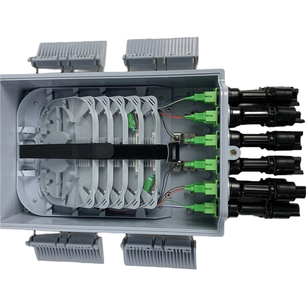
A fiber optic switch allows optical signals to be selectively switched from one fiber to another, while a fiber optic splitter divides an optical signal into multiple signals, allowing it to be transmitted to multiple devices. It is essentially a switch that operates at the optical layer of a network, rather than at the electrical layer. Conversely, it can also combine multiple signals into one. Its primary role is in Passive Optical Networks (PON), which are the foundation of. A fiber optic splitter is a passive optical component that divides a single incoming optical signal into two or more outgoing signals, or combines multiple incoming signals into one. The optical network system uses an optical signal coupled to the branch distribution. The fiber optic. While the splitter doesn't manage or direct traffic like a switch, it does allow multiple devices to access the same network connection. The devices connected to the splitter typically need to be configured to work with the shared connection, and bandwidth may be divided among the devices based on. A passive device used to split or combine signals on fiber optics may be called a splitter, combiner or coupler, but splitter is the most common term. They have been used since the 1980s to create networks and provide the technology for today's passive optical networks used in fiber to the home.
[PDF]

When comparing plate/mirror and cube beam splitters, the mirror splitters can tolerate more powerful beams of light, but the cubes have far better durability and are easier to handle. A beam splitter or beamsplitter is an optical device that splits a beam of light into a transmitted and a reflected beam. It is a crucial part of many optical experimental and measurement systems, such as interferometers, also finding widespread application in fibre optic telecommunications. Beamsplitters are often classified according to their construction: cube or plate. 📦 For purchasing, use the RP Photonics Buyer's Guide for beam splitters. It provides an expert-curated supplier directory, buyer-focused technical background information, and structured selection criteria to support professional procurement decisions. 2. Plate beamsplitters have a number of advantages over cube beamsplitters. The beam splitter splits and then recombines infrared radiation, while the detector picks up the resulting signal. It's sensitive to both intensity and frequency. Together, they decide just how accurately an instrument.
[PDF]
A fiber-optic splitter, also known as a, is based on a of an integrated waveguide power distribution device, similar to a The system uses an optical signal coupled to the branch distribution. The splitter is one of the most important in the link. It is an optical fiber tandem device with many input and output terminals, especially applicable to a passive optical network (,,,.
[PDF]
Explore the precision, applications, and design principles of beam splitters, essential for advancements in scientific research and technology. Beam splitters are integral optical components that divide a beam of light into two or more separate beams. There are two basic types of beamsplitters: Non-polarizing beamsplitters (NPBS): This type of splitter is used to divide (split) a beam into two beams and each output beam is a fraction of the incoming beam regardless of the polarizations. Non-polarizing beamsplitters are used in a variety of. 📦 For purchasing, use the RP Photonics Buyer's Guide for beam splitters. It provides an expert-curated supplier directory, buyer-focused technical background information, and structured selection criteria to support professional procurement decisions. What are Beam Splitters? A beam splitter (or. As a basic and important link in on-chip photon propagation, beam splitting is of great significance for the efficient utilization of sources and the compact integration of optoelectronic devices. It is widely used in power splitting, polarization separation, wavelength division multiplexing and. The SPIE Digital Library offers a wide range of resources on beam splitters, focusing on their design, applications, and performance across various optical systems. The principle of beam splitting is based on the manipulation of light waves using various optical materials and coatings. Their precision and versatility make them.
[PDF]

ITU & IEC allow 0. 75 dB loss per mated pair. Splitter loss values are "Typical" and include a connector in and out. These values are approximate and should not be exceeded by more than 1-1. 5 dB, which could indicate dirty connectors, bad splices, or. ITU & IEC allow 0. These are known as passive optical splitters, and they perform the function. Let's start with the simplest part: the ideal, theoretical loss caused purely by dividing the light equally among N paths. This is often called Distribution Loss or Ideal Split Loss. Understanding the types of splitters, their impact on network performance, and how to measure their losses ensures high-quality network operation and facilitates optimal splitter selection based on. Use 2×N when two inputs feed the same distribution stage. Common values: 2, 4, 8, 16, 32, 64. Wavelength is recorded in outputs for documentation. 5 dB depending on splitter type. Fusion splices often plan around 0. Optional: patch. Excess loss is the ratio of the optical power launched at the input port of the splitter to the total optical power measured from all output ports. It assures that the total output is never as high as the input. Components, such as fiber cables, splitters, and switches, introduce attenuation. The maximum allowable distance between a transmitting laser and receiver is based upon.
[PDF]
Beamsplitter coatings are specialized optical coatings applied to glass or other substrates to split incident light into two or more separate beams, typically by reflecting a portion of the light while transmitting the remainder. Beamsplitters are common components in laser or illumination systems. Beamsplitters are also ideal for fluorescence applications, optical interferometry, or life science or semiconductor instrumentation. Light. Thorlabs offers a wide range of optical beamsplitters. Our plate beamsplitters have a coated front surface that determines the beam splitting ratio while the back surface is wedged and AR coated in order to minimize ghosting and interference effects. Pellicle beamsplitters provide excellent. My question is, does anyone have any idea where to source normal hard coated beam splitter glass I could replace this one with? Or is there a film that can be applied to it? It's just a flat piece of glass that has the half silvered coating on it. This is quite common on Kalart. An Optical Beamsplitter is an optic or optical device that is used to split a beam of light in two. It is a crucial part of many optical experimental and measurement systems, such as interferometers, also finding widespread application in fibre optic telecommunications. This precise ability to split light by wavelength makes beam splitters essential in various fields, including laser systems, semiconductor.
[PDF]
This occurs because when s-polarized light hits the reflecting surface, the electric field is in the same plane as the surface. The set up is either: Camera lens - beam splitter - camera x2 Or, Beam splitter - (lens + camera) x2 I want to be able to take 2x photos at once, so the light has to go through the beam splitter. I used the polarised flexible sheet as a proof on concept, which worked but need to make it more. A beam splitter or beamsplitter is an optical device that splits a beam of light into a transmitted and a reflected beam. It is a crucial part of many optical experimental and measurement systems, such as interferometers, also finding widespread application in fibre optic telecommunications. Additionally, beamsplitters can be used in reverse to combine two different beams into a single one. The resulting beams are directed along different paths, allowing a single light. 📦 For purchasing, use the RP Photonics Buyer's Guide for beam splitters. It provides an expert-curated supplier directory, buyer-focused technical background information, and structured selection criteria to support professional procurement decisions. What are Beam Splitters? A beam splitter (or. am Splitters/Combiners. This document describes this product line, as well as general operation guidel into two output beams t beams of equal power. The standard product is designed for use in the visible spectrum 400-700 nm wavelength). The cube can only be effectively used as a splitter; used.
[PDF]

Insertion loss tells you how much weaker the signal becomes after passing through the splitter. Let's say you have a laser output at 0 dBm (which is 1 milliwatt of optical power). If you use a 1×8 splitter with ~10. 5 dB of insertion loss, the power at each output would be: 0 dBm – 10. 5. Enter excess loss from the splitter datasheet for your wavelength. Add connector and splice quantities with realistic planning losses. Include any additional component losses and an engineering margin. Enable power budget to estimate received power and margin. Press Calculate to show results above. Understanding optical splitter loss isn't just about plugging numbers into a calculator. It's about knowing what factors contribute to that loss, how manufacturers specify it, and how it impacts the overall performance and reach of your network. Ignore it, and you might find your signal too weak to. Optical insertion loss refers to the signal loss resulting from the insertion of components such as connectors or splices in an optical fiber system. Common ratios: For cascades, add losses and validate margin using the Optical Budget tool. This Fiber Optic Splitter Insertion Loss is the splitter devices loss, Considering fiber connectors or connectors+adapter insertion loss in LGX, The fiber splitter IL would be a little bigger. To make clear the basic ftth fiber splitter loss in performance, You can refer to the below loss chart.
[PDF]

An ideal optical splitter will distribute the light power according to mathematical principle. This is because each of the 8 output ports of the splitter will receive only one-eighth of the. Thorlabs' Single Mode 1x8 Fiber Optic Planar Lightwave Circuit (PLC) Splitters allow a user to split a single input signal evenly into eight output signals, which is ideal for passive optical networks (PON) and other high-channel-count applications. 1×8 splitter means it takes one input fiber and splits the signal into eight outputs. It doesn't need power — it's passive! Great for sharing one signal with many devices, like in FTTH (Fiber To The Home) networks. But light doesn't just split for free. Sharing means each output gets less than the. If we operate with absolute gains measured in relation to 1 milliwatt (mW), they are expressed in dBm, and are calculated as follows: Power Level (dBm) = 10 lg ( mW / 1 ) For “household” needs, in order not to calculate mW to dBm and vice versa every time, here's a ready-made correspondence table:. For instance, a 1:8 splitter ratio signifies an equal distribution of incoming optical power among eight output ports, with each port receiving 1/8th of the total power. It has one input port and eight output ports, making it ideal for applications where a signal needs to be.
[PDF]
