
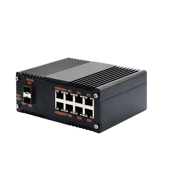
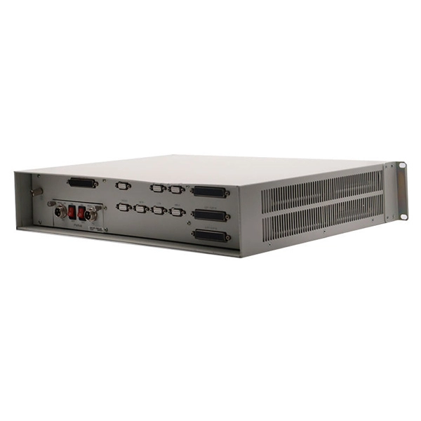
The six-phase sequence current protection tester is an advanced device used to verify complex protection devices. Its core principle lies in the simultaneous output of six independent current and voltage signals to simulate various normal and fault conditions in a power system. It not only supports. In the complex world of power system protection, the Six Phase Relay Protection Test Set has emerged as an indispensable tool for engineers and technicians. These advanced devices play a critical role in verifying the reliability and accuracy of protective relays, ensuring the safe operation of. The CMC 356 is the universal solution for testing all generations and types of protection relays. Its powerful six current sources (three-phase mode: up to 64 A / 860 VA per channel) with a great dynamic range, make the unit capable of testing even high-burden electromechanical relays with very. JBC-806tester can simultaneously outputstandard six-phase current and six-phase voltage with 30A/phase current and 125V/phase voltage. With its six-phase output, this tester provides comprehensive testing capabilities, making it an essential instrument for ensuring the. nation in general. Not influenced by load, they contribute to protection speed and sensitivity. However, sequence components are present for a range of conditions, not only faults: open pole, load and line unba ance, breaker pole scatter, and current transformer ratio errors and saturation, to name.
[PDF]
of relay protection coordination for a PV power plant connected to the distribution network is presented. In recent years, installation of PV power plants in the distribution network has increased significantly. I.
[PDF]

This video provides a detailed walkthrough of designing and simulating an automatic light control system using Light-Dependent Resistor (LDR) and Triac in Proteus Software. Last updated on 13 August 2025 by Admin-Lavi Leave a Comment This article talks about Light Controlled Switch Circuit using IC LM311 and LDR. It simple and very useful and it feel light change near it. We find this circuit in many place like automatic light, street lamp and security system. Main. ABB's Control Room offering includes a comprehensive range of solutions designed to optimize the operator workspace for critical 24/7 processes across various industries. The project demonstrates how to create a smart lighting system that turns on/off automatically based. more This video. The Intro Screen changes as you play with it. It has a Play Area and a Control Area. A Construction Area creates a building space for components added from a Circuit Component Toolbox. Build and navigate your circuits there. If Voltmeters and Ammeters are out of the toolbox, you can take. Common sense schematics let you name a node "+5V" and know that the simulator will do the right thing automatically, keeping your schematics compact and elegant. This circuit activates or deactivates connected loads, such as LEDs or light bulbs, based on ambient light levels.
[PDF]

Protective relays are special electrical devices used to detect faults in power systems and quickly disconnect faulty parts to prevent damage. These relays sense abnormal conditions like overcurrent, under-voltage, or short circuits and send a signal to circuit breakers to open the. Electromechanical protective relays at a hydroelectric generating plant. The relays are in round glass cases. The rectangular devices are test connection blocks, used for testing and isolation of instrument transformer circuits. In electrical engineering, a protective relay is a relay device. Protective Relay Definition: A protective relay is an automatic device that senses abnormal conditions in electrical circuits and triggers actions to isolate faults. Types of Protective Relays: Protective relays are categorized by their mechanism (electromagnetic, static, mechanical) and function. Combines protection, sensors, control power, and circuit breaker in a single package Typically added to a breaker close circuit to prevent accidental reclosure after a trip. Three fundamental components required for each circuit breaker. It initiates the operation of circuit breakers to isolate the affected section.
[PDF]

This guide describes the general requirements, functional and technical performance requirements, test requirements, labeling and packaging requirements, transportation and storage requirements, supply integrity requirements, and quality assurance requirements for hybrid high-voltage. This guide describes the general requirements, functional and technical performance requirements, test requirements, labeling and packaging requirements, transportation and storage requirements, supply integrity requirements, and quality assurance requirements for hybrid high-voltage. Guide for Technical Requirements for Hybrid High-Voltage Direct Current Transmission Protection and Control Equipment This guide describes the general requirements, functional and technical performance requirements, test requirements, labeling and packaging requirements, transportation and storage. purpose of this white paper is to aid WECC members (Specifier) in specifying and applying relay systems that will provide adequate protection of extra-high voltage (EHV) on 345-kV or higher transmission lines and comply with the NERC Reliability Standards. The recommendations in this white paper.
[PDF]
As a critical component in high-speed networks, fiber optic patch cords require micron-level precision. This guide unveils the complete production workflow compliant with **IEC 61754** and **Telcordia GR-326-CORE** standards, featuring proprietary quality control. If you've ever troubleshot a fiber optic network only to find that a microscopic dust particle caused the entire system failure, you understand why IPC-8497-1 exists. This standard represents the industry's collective wisdom on how to properly clean and assess contamination in optical assemblies. For harsh environments or other data center and IT networking applications where there is a greater risk of damage to your fiber optic network, armored fiber optic cables deliver the protection you require. Built with a steel-armored layer that provides extra crush and rodent resistance, these. Welcome to be our agent! Fiber optic patch cords, also known as fiber jumpers, are essential components in high-speed data transmission networks. Their performance directly impacts signal quality, insertion loss (IL), and return loss (RL). At ZION Communication, we design and manufacture a full range of fiber patch cords for: This guide will help you quickly understand the main types of. Ensuring the performance and reliability of fiber optic patch cords is fundamental to optical network integrity. 6-Step Manufacturing.
[PDF]

The circuit diagram of the protective relay is made up of current transformer primary windings, current transformer secondary windings, relay operating coils, circuit breakers, and the tripping circuit. The relays are in round glass cases. The rectangular devices are test connection blocks, used for testing and isolation of instrument transformer circuits. In electrical engineering, a protective relay is a relay device designed to trip a circuit breaker when a fault is detected. : 4 The first. The working of a protective relay is based on continuous monitoring of electrical quantities such as current, voltage, frequency, and power. A typical protective relay circuit is shown below: Protective Relay Circuit Diagram The first part of the circuit consists of the primary winding of a CT. A relay is a four-terminal electrical switch, used to control any electrical circuit with an independent low-power signal and also to control various electrical circuits with a single signal. The terminals of the relay mainly include; common, coil, NO (normally open) & NC (normally closed). It functions as a watchdog by constantly surveying multiple system components including voltage, current, frequency, and phase angle. During a fault condition, there is a change. Protective relays and devices have been developed over 100 years ago to provide “lastline”of defense for the electrical systems.
[PDF]

The fiber optic cable core is the physical glass medium that transports optical signals from an attached light source to a receiving device. The light is transported along the optical fiber via its smallest and most crucial component, which is called the core. The modern digital world relies heavily on fiber optic cables, which serve as the high-speed backbone for global communication. Professionals in telecommunications, data centers, and network infrastructure must understand the core functions and why they are fundamental to their fiber optic. A fiber optic cable consists of five basic components: the core, the cladding, the coating, the strengthening fibers, and the cable jacket. When searching for a fiber optic cable, we need to pay attention not only to the connectors, such as SC to ST fiber cable, LC to SC fiber patch cable, or SC to. The reason is that cores are basically hidden components located that receive the light signals. Don't worry, in this guide, we'll discuss in detail what the fiber optic core is and its role in data transmission. Moreover, we'll also explore the different types of fiber optic cores available as. The core of a conventional optical fiber is the part of the fiber that guides the light. It is a cylinder of glass or plastic that runs along the fiber's length. The core is surrounded by a medium with a lower index of refraction, typically a cladding of a different glass, or plastic.
[PDF]
Beam splitters are classified by construction (plate, cube, pellicle, polka dot) and by function (standard, non-polarizing, polarizing, dichroic). Construction determines ghosting, damage threshold, and form factor. Function determines how polarization and wavelength are. Beamsplitters are optical components used to split incident light at a designated ratio into two separate beams. Additionally, beamsplitters can be used in reverse to combine two different beams into a single one. Beamsplitters are often classified according to their construction: cube or plate. A beam splitter or beamsplitter is an optical device that splits a beam of light into a transmitted and a reflected beam. It is a crucial part of many optical experimental and measurement systems, such as interferometers, also finding widespread application in fibre optic telecommunications. This division allows for the simultaneous analysis or utilization of the light's properties along two separate paths. These versatile tools can split both laser and regular light, depending on the application in question. Its fundamental purpose is to precisely control the path and intensity of light, making it a ubiquitous component across various optical systems. For a lossless beam splitter, R + T = 1. When comparing beam splitters, always check whether the specified R/T ratio is for unpolarized light or for a specific polarization. The numbers can differ.
[PDF]

An elevator data communication system is configured to communicate between a plurality of elevator systems and a datacenter remotely located from the plurality of elevator systems. WAN – Wide area network is similar to a LAN but is not limited to a single location. It can also consist of several LANs which are interconnected. Usually, it is the only way how to contact the outside world and get help when you are trapped in the elevator. But many changes and exciting new challenges are coming in the field of elevator. “THE LONGEST RUNNING PUBLICATION FOR THE VERTICAL TRANSPORTATION INDUSTRY SINCE 1953. ” Open and standard communication protocols are vital for interoperability in building automation and elevators. The OSI seven-layer model frames protocol design but compliance alone does not guarantee. Elevators are essential in most modern buildings, but they need communication systems that meet code requirements. Here's how new features are making compliance easier—and delivering a new revenue stream. More sophisticated and effective communication solutions are needed to manage the increasing. Technical systems are, in general, becoming ever more complex. Electronic systems – usually equipped with tiny embedded microprocessors – are implementing new functions, increasing convenience or improving system safety and reliability.
[PDF]
Beamsplitters are commonly employed in lasers to create different beam paths, achieving this effect by dividing the laser beam into multiple segments and then recombining them. This allows the direction and intensity of the beam to be adjusted with outstanding precision and. Beamsplitters are fundamental components in optical engineering, serving to precisely divide a single input beam of light into two distinct output beams. This division allows for the simultaneous analysis or utilization of the light's properties along two separate paths. It is a crucial part of many optical experimental and measurement systems, such as interferometers, also finding widespread application in fibre optic telecommunications. In its. This article explains how to create a beam splitter cube in Sequential Mode. One of the biggest challenges for modeling such a system is that multiple ray paths cannot be simultaneously traced in Sequential Mode. These versatile tools can split both laser and regular light, depending on the application in question. Beamsplitters are often classified according to their construction: cube or plate. Beam splitter divides a beam of light into two or more separate beams. Beam splitters can be made from different materials and are often coated with thin layers of metal or dielectric materials.
[PDF]

The presence of a strong sealant in the closure helps prevent water and air from entering it. Some splice closures have all cables entering into one end, usually called dome closures or sometimes called a butt closure, while some have cable entries on both ends, sometimes called inline closures. Inline closures are used in applications where two identical cables are spliced and an inline. Fiber splice joint closures are vital but often overlooked. It plays a crucial role in keeping networks running smoothly, even in the harshest conditions. Let's explore what they are, why they matter, and how technological advancements are making them even better. Fiber splice joint closures are. A fiber optic splice closure is a protective enclosure designed to house and protect fiber optic splices and, in some cases, passive optical components. It provides mechanical protection, environmental sealing, and internal fiber management for spliced optical fibers. Fiber optic splice closures have been widely used in various fields such as communication, network systems, CATV, etc. There are. CommScope addresses these challenges with a comprehensive family of fiber splice closures that prioritize essential criteria: reliability, installability, flexibility, and speed of deployment. Whether underground, aerial, or in manholes, splice closures are the first line of defense against environmental threats to your fiber.
[PDF]

A fiber optic adapter (or fiber coupler) is a passive component used to join and align two optical connectors. It plays a key role in maintaining core-to-core alignment, allowing optical signals to pass through with minimal insertion loss and stable performance. Fiber optic adapters play a critical role in ensuring stable and low-loss fiber connections. This guide covers adapter types, selection criteria, cleaning tips, FAQs, and B2B customization options to help businesses build reliable and scalable fiber networks. They enable seamless and reliable optical signal transmission between different fiber optic cables, connectors, or devices., two fiber connectors) such that light can reliably pass from one to the other with minimal insertion loss and maximum return loss. A fiber-optic adapter connects two optical fiber connectors in the fiber optic lines. Bare fiber adapter is used as the medium to temporarily link the bare optical fiber to fiber optic equipment. Available with FC, SC, ST. LC, MU, SMA connectors with round or square type press button. This article discusses their purposes, features, types, and how to choose and clean them. What is a Fiber Optic Adapter?.
[PDF]
