Picking up the best router for fiber internet isn't just about going to the market and choosing one of the best wireless routers. Instead, you need to carefully look at its specs, performance, and the type of securit.
[PDF]
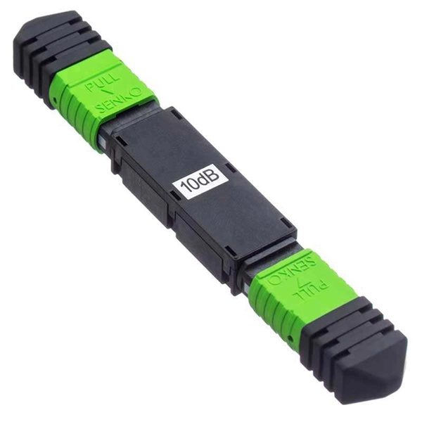
The input beam is spatially separated into two orthogonally polarized beams, diverging at an angle determined by the prism geometry and the material's properties. A beam splitter or beamsplitter is an optical device that splits a beam of light into a transmitted and a reflected beam. It is a crucial part of many optical experimental and measurement systems, such as interferometers, also finding widespread application in fibre optic telecommunications. a laser beam) into two (or sometimes more) beams, which may or may not have the same optical power (radiant flux). This division allows for the simultaneous analysis or utilization of the light's properties along two separate paths. When light enters a beam splitter, it is either reflected or transmitted, according to the optical properties of the beam splitter's material and coating. Free-space beam splitters.
[PDF]

It's called a breaker box, and even though it might not look very exciting on the outside, what's behind that little door is the heart of your home's electrical system. Bottom Line Up Front: Your home's distribution box (electrical panel) is typically located in the basement, garage, utility room, or mounted outside near your electrical meter. To find it quickly, look for a rectangular gray metal box about the size of a medicine cabinet, often positioned close to. Electrical panel boxes, aka breaker boxes, can be on a wall in an out-of-the-way area of your home. You can find electric panels inside cabinets, behind refrigerators, or inside clothes closets in older homes. Current National Electrical Codes (NEC) allow none of these locations. Electrical panels. The electrical panel is the central hub that distributes electricity throughout the house. Knowing where to find your electrical panel in your home helps in case of emergencies and routine maintenance. Panels are commonly found in garages, basements, utility rooms, and outdoor walls. Understanding how your electrical panel works can help you troubleshoot issues, perform basic maintenance, and know when to. When something electrical goes wrong in your home—like a tripped circuit or sudden power outage in one part of the house—most people instinctively head to that gray metal panel, often hidden in a basement, utility closet, or garage. Having the breaker box.
[PDF]
Cable TypePrice Range (USD/meter)Simplex / Duplex Indoor Cable$0. 30Single-mode Outdoor Cable$0. 50Multimode (OM1/OM2/OM3)$0. 60Armored Cable (Steel Tape / FRP)$0. 50 These are indicative prices. Buyers typically pay for fiber optic cable by length, fiber type, and installation complexity. Main cost drivers include cable grade (indoor vs outdoor, armoured), distance, and labor for trenching, splicing, and termination. Data aggregated from Q1 2026 contractor invoices across Texas, Ohio, and North Carolina. Cost per foot of fiber. How Much Does Fiber Optic Installation Cost Per Foot? Cable Material Costs: Installation Costs by Method: Prices can range from $1 to $50+ per linear foot depending on the method and complexity. The initial cost of installing fiber optic cables can vary depending on the chosen installation method. Cable installation price refers to the total cost of deploying fibre or copper cabling across a site. It includes labour, materials, termination methods, routing complexity, and any environmental factors such as trenching or conduit work. When you plan a structured cabling project, the cost of. Because the core is wider and harder to manufacture to 2025 standards, it's a jump in price: $1. Armored cables: If there's any chance of a shovel or a rat hitting that line, you need steel tape armor. That “insurance” That 'insurance' bumps the price to $1. 50 per meter, depending on several variables.
[PDF]
This video shows real on-site footage of electrical installation, demonstrating safe and standardized wiring methods used by professionals. more Learn how to wire a distribution box step by step! This video shows real on-site footage of. Material preparation: Prepare the required circuit breakers, wires, wiring ties and other materials, and ensure that they meet the design drawings and installation requirements. Location determination: Determine the installation position of the circuit breaker according to the position of the. Learn how to install a distribution box safely and correctly. Covers wiring, placement, standards, and expert tips for a compliant setup. A distribution box is the heart of any electrical system. It takes the incoming power and safely distributes it to different circuits throughout your building. It serves as a central hub for distributing electricity throughout a building, ensuring that power is delivered safely and efficiently to all the required locations. This video highlights the installation process for CANTEX Exposed Weatherproof PVC electrical boxes. When an electrical connection is needed outside of a home, commercial or industrial building---or anywhere it might be exposed to the elements, weatherproof electrical boxes and covers are required. It has three categories: residential, commercial and industrial electrical distribution boxes, all of which play important roles in their respective electrical.
[PDF]
This guide summarizes field-proven rules for AI/AO/DI/DO wiring, shows how to choose between NO/NC contacts under the fail-safe principle, and explains how to decode typical cable schedule entries. Instrument installation with the associated cable installation/electrical signal and control wiring should be carried out by skilled personnel who are acquainted with the safety requirements and regulations for the plant site for that specific project. Generally instrument cabling is usually run in. Few factors are to be considered or taken care of while wiring a field instrument to control panel. Based on noise susceptibility limits (NSL) according to IEEE 815 standard, various field instrument signals are classified as below. Noise Susceptibility Limit Grounding of the signal cable Type of cable Cable Terminations Based on noise susceptibility limits (NSL). Note how the hoop-shaped “jumper” wires are all cut to (nearly) the same length, and how each of the wire labels is oriented such that the printing is easy to read: This next photograph shows a great way to terminate multi-conductor signal cable to terminal blocks. Each of the pairs was twisted. A well-designed and properly installed instrument junction box is crucial for the efficient operation and maintenance of electrical systems. Level 1: High to medium susceptibility Level 2: Low susceptibility.
[PDF]

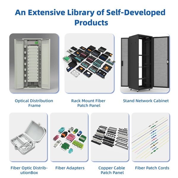
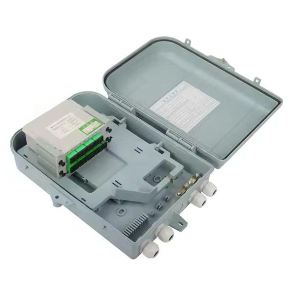
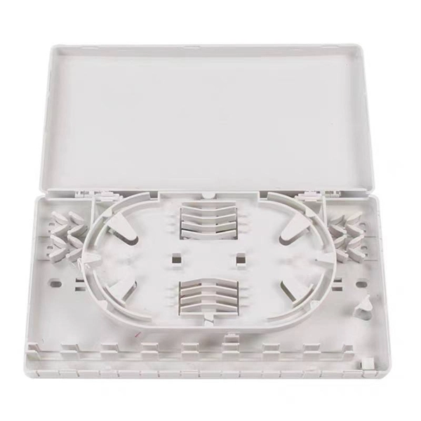
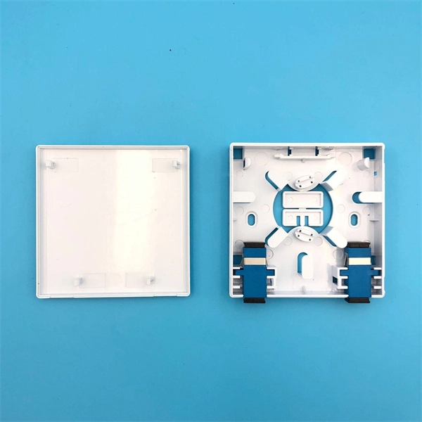
Extending the fiber through the box makes use of a cable entry gland. Fasten the cable to the clamps or ties to assure the cable is immovable. Cable must be properly minimum radius (usually ≥30mm for standard fiber). Remove the cable jacket and buffer coating material. Thus, a fiber termination box is used to terminate the optical fiber cables in the field and connect them to the pigtail by splicing. After an optical cable arrives at the user's end, it is fixed in the terminal box. Fiber adapters: These are used to connect the fiber optic cables to the fiber termination box and should comply with industry. Teleweaver emphasizes the importance of choosing the right FTB based on specific requirements. The common types include: Wall-Mounted FTBs: Ideal for residential and small-scale applications, these are compact boxes designed to be mounted on walls for easy access and space-saving cable management. To address this problem, the fiber termination box (FTB) was created to protect the fragile fiber terminals and provide a simple and clear way to manage the incoming and outgoing cables. more Order it here: https://www. This video shows you a step-by-step instruction on how to terminate 12 strands single mode fiber cables, splicing them with fiber optic pigtails.
[PDF]
This video shows real on-site footage of electrical installation, demonstrating safe and standardized wiring methods used by professionals. more Learn how to wire a distribution box step by step! This video shows real on-site footage of. A distribution box is the heart of any electrical system. It takes the incoming power and safely distributes it to different circuits throughout your building. Whether in a home or an industrial facility, this box keeps your electrical setup organized, functional, and efficient. However, the key to. In this video, we'll walk you through the process of wiring a home distribution box with a detailed connection diagram. What is Distribution Board? Distribution board. An electrical panel box, also known as a breaker box or a distribution board, is a crucial component of any electrical system. It serves as a central hub for distributing electricity throughout a building, ensuring that power is delivered safely and efficiently to all the required locations. A distribution board (also known as a service panel or breaker box) is a centralized collection of circuit breakers, fuses, and/or relays used to control and protect the wiring in a home. The diagram. Electrical wiring powers everything in your home, from lights and outlets to major appliances. We'll break down the key parts of a home.
[PDF]
The fiber cores of GYTC8S53 fiber cable is from 2 cores to 288 cores GYTC8S53 is a self-supporting fiber optical cable for outdoor use. Commonly referred to as figure 8 cable, figure 8 fiber cable, figure 8 aerial cable, self-supporting figure 8 cable, or simply figure 8 optical cable, this ingenious structure combines optical fibers with an integrated messenger wire in a distinctive “8” cross-section. This self-supporting design. Hunan GL Technology Co., Ltd Supply 2-144 Cores GYFTC8S Aerial Stranded Figure 8 Fiber Optic Cable With Factory Price, Support OEM, All the figure 8 cables supplied from GL FIBER are complied with IEC 60794-4、 IEC 60793、TIA/EIA 598 A standards. In the GYFTC8S cable, single-mode/multimode fibers are. GYTC8Y is a typical self supporting outdoor fiber optic cable with features of moisture resistance and crush resistance suitable for aerial application. The stranded wires as the supporting part are completed with a polyethylene (PE) sheath to be figure 8 structure. After being coated with steel tape longitudinally, a layer of PE inner sheath is extruded, and then a single layer or double layer thin round steel tape armor is longitudinally wrapped After installation, the. l fibers in loose tubes filled with interstitial gel. Aluminum moisture barr er tape or steel tape armoring options are availa le. A steel messenger wire provides tensile strength. It can work at the temperature from -10 to +70℃.
[PDF]
Explore verified suppliers offering low-price fiber optic splice boxes, ideal for wholesale. With options from 24 to 144 cores, start your purchase from 1 unit at an average price around $17. TAKFLY COMMUNICATIONS CO. com! Source over 176 fiber-optic splice closures for sale from manufacturers with factory direct prices, high quality & fast shipping. We support our B2B partners with OEM branding, custom configurations, and bulk order discounts, delivering factory-tested solutions for large-scale. COYOTE Closure, 288f/576f ribbon max, Buffer Tube: 8. 5″ x 22″, Includes (1) 3 Section End Plate, (1) Blank End Plate, Organizer, and Lock Tape sealant. FOSC 600 D Dome Closure, 648ct Single/1728ct Ribbon, 8 Ports, Loaded Without Trays, 4 Ground Lugs, 32. 79″, Price Per Ea. ZIP code to view pricing. ZIP code to. Budco is a stocking distribution company for broadband tools, fiber optic tools and cable tools. Since 1970, Budco has provide cable construction tools, cable installation tools, and cable identification tools including fiber optic test equipment and tools for the telecommunications industry. We. This fiber optic splice box is an outdoor fiber optic splice closure used to protect the twisting and joining (splicing) of fiber optic cables. These splice boxes are not made for in-house, off-the-shelf cabling solutions. Instead, they are for installation by professionals laying new fiber optic.
[PDF]
These screws should be 1 to 1. 5 inches long to penetrate the box and embed into the center of the stud without protruding out the back. When attaching boxes to metal studs, the preferred fastener is a self-tapping or self-drilling metal screw, such as a #6 or #8 size with a pan or. These screws should be 1 to 1. All sorts of grounded electrical metal things are mounted with self-drilling or self tapping screws that do not have 32 threads. Leviton Comment: We are covering Articles 312. 10 Screws or Other Fasteners. Screws or other fasteners installed in the field. The length of the device screw varies based on the box depth and its recess from the finished wall surface. Standard installations often use screws between 1/2 inch and 3/4 inch long, but deeper boxes or those requiring adjustment spacers may necessitate screws up to 2 inches. Using a machine screw. These standard metal boxes have been secured by driving self-tapping screws through the 1/8-inch diameter mounting holes in the side of the box and into the horizontal metal stud. Code Change Summary: Changes were made to the. My plan to ground the outlet is to use a self-tapping metal screw fixed to the back of the box. Is this a proper method of connecting the outlet ground. The old boxes have tiny threaded holes at the front of the box, but they are too small for a standard machined ground screw. The threads are a 10/32" size thread. The 4020513001K.
[PDF]

The Optical Time Domain Reflectometer (OTDR) is useful for testing the integrity of fiber optic cables. It can verify splice loss, measure length and find faults. The OTDR is also commonly used to create a "picture" of fiber optic cable when it is newly installed. The Contractor tasked to perform testing or splicing on any fiber optic cable will follow these testing standards to fulfill their contractual obligations. The Contractor must utilize the correct equipment and testing techniques to gain acceptance, or the work cannot be approved. Later, comparisons can be made. For every fiber optic cable plant, you will need to test for continuity, end-to-end loss and then troubleshoot the problems. If it's a long outside plant cable with intermediate splices, you will probably want to verify the individual splices with an OTDR also, since that's the only way to make. ic system. Fiber optic testing of a newly installed system not only verifies that the system meets its design requirements, but also creates a performance baseline for all future testing and troubleshooting of t at system. What is Fiber Optic Splicing and Why is it Needed? – #1. Use and Maintain Your. This guide reveals the secrets to fusion splicing with little fluff—just proven, straightforward techniques refined from years of work in the field. The guide provides the complete workflow, covering safety precautions, tool selection, fiber preparation, fusion operation, quality control, and.
[PDF]

When switching to fiber internet, many users wonder if they're able to use their own router instead of the one provided by their internet service provider (ISP). In this guide, we'll explain router compatibility, setup steps and whether upgrading your router is necessary to maximize fiber speeds. Selecting a single router can be challenging, as there are most likely many that fit the requirements you want. We've done the research for you and put together this in-depth guide that lists multiple options, their details, reviews, and pros and cons. This should help you make an informed decision. Unlike cable internet, fiber connections do not require a cable modem. Instead, you simply plug a wireless router into the ONT provided by your ISP, set it up, and start using the internet. But if you're unsure which router to get, you're in the right place. Instead of using your old router, a high-performance Wi-Fi router designed for fiber optic internet will ensure you seamless streaming, online gaming, and remote work all. This article provides a comprehensive review and buying guide designed to assist in identifying the best routers for fiber internet. We will explore key performance metrics, essential features such as Wi-Fi standards and port configurations, and examine a range of router models optimized for fiber. Yes, you can often use your existing router with fiber optic internet, but there are crucial considerations. This guide will break down everything you.
[PDF]