
This guide covers everything: what fiber optic pigtails are, how they differ from patch cords, which connector and polish type to specify, how to choose between mechanical and fusion splicing, and the real-world applications where pigtails are the right call. In this guide, we cover the basics of fiber optic splicing, how to perform splicing using two different methods, and finally some best practices to perform good fiber splicing. What is Fiber Optic Splicing and Why is it Needed? – #1. Whether you're building out an ODF. Think of a fiber optic cable splice as the seamless stitching that keeps data flowing through the delicate threads of a network—like a master tailor joining fabric with precision. Whether repairing a broken cable or extending a fiber run, fiber optic splicing ensures light signals travel. Fibre optic splicing is an essential skill in the world of modern telecommunications, offering a reliable method to connect optical fibres for seamless data transmission. As the demand for high-speed internet and robust communication networks continues to grow, learning to splice fibre optics is. In this guide, you will find a chronological description of the fusion splicing process, the principal technical standards, and answers to the real-life questions network engineers and procurement teams may have. Therefore, we will also touch on cost factors, risk management, and best practices in.
[PDF]
Fiber optic splicing is the process of joining two fiber optic cables together so that light signals can pass with minimal loss or reflection. Splicing is typically required during cable installation, maintenance, or network expansion. Another method of connecting optical fibers is termination or connectorization, which consists of processing the end of a fiber optic bundle so that it can be connected to other fibers or devices through fiber optic. When deploying fiber optic cabling, one of the most critical decisions is how to terminate the fiber—either by splicing or using connectors. Both techniques have their advantages and are suited for different applications, but understanding which method to use can greatly impact the network's. Fiber optic splicing, crucial for maintaining seamless connectivity in modern communication networks, primarily uses two methods: fusion splicing and mechanical splicing. Fusion splicing provides a low-loss, highly reliable connection by melting and fusing fiber ends, making it ideal for long-haul. As fiber optic connections become increasingly mainstream, the need to connect fiber optic cables to one another — or splicing — is also on the rise. Get the wrong connector type, the wrong polish, or skip proper fusion splicing technique—and you're looking at elevated signal loss, increased back reflection, and a.
[PDF]

Because fiber optic cables don't come in one continuous length, sections must be joined together through splicing. This process fuses two glass strands so light signals can travel through them without interruption. Below is a detailed look at each step of fiber optic network construction, including key terms and methods used across the industry. Engineers and. We are experts in the installation and use of fiber optic cable to residences, apartment buildings, businesses and cell sites. We complete complex construction projects consisting of aerial and underground deployments in varied, often difficult, working environments. Our services include everything. The Fiber Optic Association, Inc. (FOA) was founded in 1995 to help develop the workforce to build the fiber optic networks to support a rapid expansion in communications and the Internet. Delivers state-of-the-art fiber optics solutions by developing high-tech equipment and subcontractor expertise. Utilizes state-of-the-art technologies to splice a wide variety of different. This recommended practices document is a comprehensive manual for optical fiber construction and testing. Sections are included for project management; cable handling, testing and equipment; overhead cable placement; underground cable placement; underground enclosures; bonding and grounding; cable. 4. FO-VC2 JOINT USE - VERICAL MIDSPAN CLEARANCES 48. FO-GB GROUNDING AND BONDING 49.
[PDF]
Main cost drivers include on-site labor, specialized fusion splicing, testing, and any necessary restoration of network performance. This guide provides practical cost ranges in USD with clear low–average–high estimates to help budgeting and planning. Fiber optic splicing costs vary widely depending on project size, location, fiber type, and site conditions. For most commercial projects, expect to pay $50–$150 per fusion splice point — but that number can swing in either direction based on the factors below. The "per splice" rate is the most. There are two primary methods of splicing fiber optic cables: fusion splicing and mechanical splicing. Each method has distinct characteristics and costs associated with it. Fusion Splicing: This method involves aligning two fiber ends and using an electric arc to melt them together, creating a. Adtell Integration is capable of supporting your fusion splicing requirements whether they require Singlemode, Multimode, or Ribbon Splicing. Fusion Splicing Services: Contractor/Customer Fusion Splicing & Installation Services: Adtell integration offers nationwide fusion splicing services. Specifically fiber used for internet. -W2 employee for a decent size telecommunication contractor, all.
[PDF]

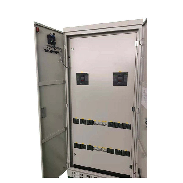
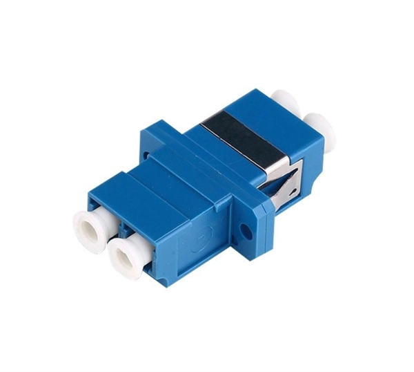
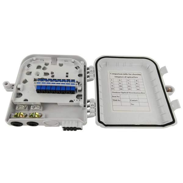
When the heat-shrinkable tube is tightened after splicing, the residual pollutants (such as tiny sand particles) will press the optical fiber and cause the optical fiber to deform, so the splicing loss will increase. At this time, the fiber needs to be cleaned. A fiber optic pigtail is a fiber optic cable with one end terminated with a factory-installed connector and the other end unterminated. As a result, the connector side can be connected to equipment, while the other side is fused in the case of fusion splicing and a mechanical connection in the case. Executive Summary: A fiber optic pigtail is one of the most commonly specified yet least understood components in structured cabling. The guide provides the complete workflow, covering safety precautions, tool selection, fiber preparation, fusion operation, quality control, and. Removes the protective coating to expose the bare fiber for splicing, ensuring no scratches or nicks. Produces a clean, precise fiber end face, critical for low-loss fusion or mechanical splicing. Precisely aligns and fuses fiber ends to form a stable, low-loss connection suitable for long-term. The scientific fiber coiling method can make the optical fiber layout reasonable, the additional loss is small, can withstand the test of time and harsh environment, and can avoid the phenomenon of fiber breakage caused by extrusion. Optic Fiber Management Rules 1. Coil the fibers along the.
[PDF]
Fiber optic communication relies on transmitting information as pulses of light through thin strands of glass or plastic called optical fibers. Instead of using electrical signals (like in traditional copper wires), it uses electromagnetic radiation in the form of light. This method encodes data into light signals by modulating properties like wavelength, phase, and polarization. The light signals propagate to the receiver through the fiber optic cable. Optical fiber. Okay, let's break down the use of electromagnetic radiation (specifically light) in fiber optic communication. It's a fascinating and crucial technology! Here's a comprehensive explanation, covering the basics, the types of light used, how it works, advantages, and some challenges. The light is a form of carrier wave that is modulated to carry information. This method of data transmission has gained substantial significance in modern communication networks due to its capacity to deliver high-speed internet and other forms of. By using the phenomenon of total internal reflection, light can be transported over long distances without reduction of the energy density due to divergence of the beam. The principle has been known for a long time, but the topic was greatly boosted by the invention of the laser.
[PDF]

Network segmentation with switches involves dividing a network into smaller, isolated segments to enhance security, improve performance, and simplify management. Learn how to configure a switch for network segmentation effectively by using VLANs, subnetting, and access control lists (ACLs). You may. to communicate with each other. VLA h or complete physical network. When you physically separate a network, the devic s are assigned to a switch port. However, when a network is separated using VLANs, the devices are logically separated by n of the VLANs is not mandatory. VLANs can also extend. Explore how Versitron single fiber media converters support fiber optic packet forwarding, VLAN tagging, signal amplification, and robust network segmentation—ideal for scalable and secure data infrastructure. Setting up a VLAN on a fiber optic switch is very similar to setting up on any other type of switch, but it's important to make sure the switch supports VLAN functionality. The. By segmenting a network into VLANs, you will increase usable network bandwidth, resources, and performance through the reduction of broadcast traffic. Routers also break up broadcast domains. Routers operate at Layer 3, forwarding packets based on IP addresses, not MAC addresses. A router will. Step-by-step instructions for configuring VLANs using network hardware. Allocate unique segment identifiers directly through your device's interface to minimize broadcast domains and reduce.
[PDF]
In this guide, you will find a chronological description of the fusion splicing process, the principal technical standards, and answers to the real-life questions network engineers and procurement teams may have. 📦 For purchasing, use the RP Photonics Buyer's Guide for fusion splicers. It provides an expert-curated supplier directory, buyer-focused technical background information, and structured selection criteria to support professional procurement decisions. This article explains the principle of fusion. Fusion splicers play a crucial role in the field of optical fibre communications by enabling the permanent bonding of two strands of glass fibre to create a continuous pathway for light to travel through. This process is achieved through precise alignment and fusion of the fibre ends using an. Fusion splicing is the process of fusing or welding two fibers together usually by an electric arc. Fusion splicing is the most widely used method of splicing as it provides for the lowest loss and least reflectance, as well as providing the strongest and most reliable joint between two fibers. Each splicer is equipped with a cleaver and stripper, conveniently includes in a single case. The goal is to align the microscopic glass cores (typically.
[PDF]

The Optical Time Domain Reflectometer (OTDR) is useful for testing the integrity of fiber optic cables. It can verify splice loss, measure length and find faults. The OTDR is also commonly used to create a "picture" of fiber optic cable when it is newly installed. The Contractor tasked to perform testing or splicing on any fiber optic cable will follow these testing standards to fulfill their contractual obligations. The Contractor must utilize the correct equipment and testing techniques to gain acceptance, or the work cannot be approved. Later, comparisons can be made. For every fiber optic cable plant, you will need to test for continuity, end-to-end loss and then troubleshoot the problems. If it's a long outside plant cable with intermediate splices, you will probably want to verify the individual splices with an OTDR also, since that's the only way to make. ic system. Fiber optic testing of a newly installed system not only verifies that the system meets its design requirements, but also creates a performance baseline for all future testing and troubleshooting of t at system. What is Fiber Optic Splicing and Why is it Needed? – #1. Use and Maintain Your. This guide reveals the secrets to fusion splicing with little fluff—just proven, straightforward techniques refined from years of work in the field. The guide provides the complete workflow, covering safety precautions, tool selection, fiber preparation, fusion operation, quality control, and.
[PDF]
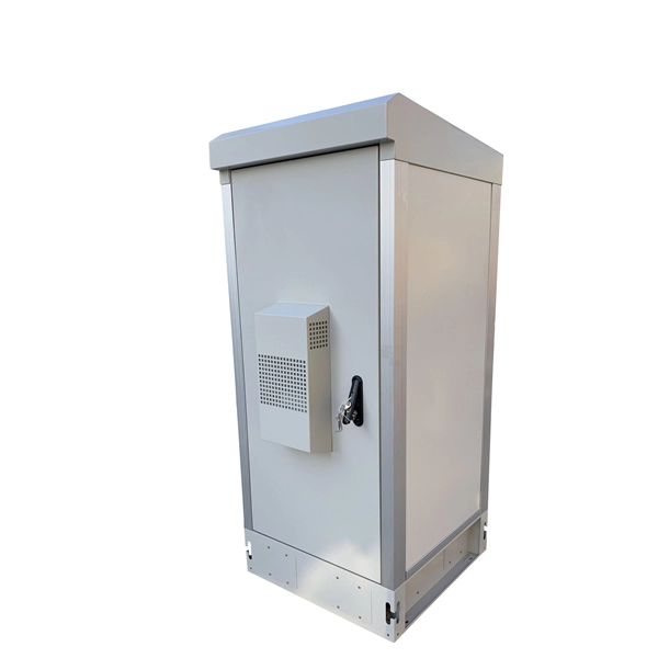
Steel tape armored (STA) fiber optic cable is a reinforced cable structure designed for underground environments where mechanical protection is critical. This cable design is commonly installed inside underground ducts or conduits where fiber cables require protection from external pressure and environmental conditions. GYTS. nded water-blocking tape and corrugated, laminated steel tape. The cable features steel wire strength mem member with water swellable threads and water swellable tape. Helically applied wa erblocking e-glass non metallic strength members with ripcord. Corrugated Steel Tape (CST) armouring and. ape Armored Cables is a central tube cable using optical fibres presented in loose tube and surrounded by Steel Tape armor. To protect the optical fibres from water ingress, the tube is filled with a thix tropic gel, and is enclosed in a thermoplastic sheath. The cables have embedded strength. ESCAB GYTY133 - fiber cable is stranded loose tube structure with steel tape double sheaths, the loose tube stranding technology make the fibers have good secondary excess length and allow the fibers free movement in the tube, which keeps the fiber stress-free while the cable is subjected to. Corrugated steel tape armored fiber optic cables are engineered for durability and performance in demanding environments. These cables combine optical transmission efficiency with robust mechanical protection, making them ideal for outdoor, underground, and industrial installations.
[PDF]
Algeria's import market for optical fiber cables is highly dependent on a single source. In value terms, China constituted the largest supplier, comprising 81% of total imports. 5% share, followed by Turkey with a 2. The Telecommunications and Information Technology (IT) segments dominate Algeria's ICT sector. The country's infrastructure primarily relies on 3G and 4G LTE for mobile telecommunications and ADSL and fiber for fixed telecommunications. Algeria connects to Europe via four fiber-optic submarine. The Algeria Optical Fiber Market is experiencing steady growth driven by increasing demand for high-speed internet services and advancements in telecommunications infrastructure. The market is witnessing significant investments in the deployment of optical fiber networks across the country to meet. Algiers, Algeria | Algeria is stepping decisively onto the continental stage, reinforcing its ambition to become a pivotal hub in intra-African trade under the African Continental Free Trade Area (AfCFTA), the most ambitious economic integration project in Africa's history. From 2020 to 2024, the country's import supply was overwhelmingly dominated by China, which accounted for 81% of import value. Algeria's own export activity in this sector is. Trans-Saharan optical fiber backbone: Algeria deploys its 2600 km and offers its assistance.
[PDF]
A fiber media converter takes an Ethernet signal on copper (RJ-45) and converts it to an optical signal on fiber, or vice versa. There are also fiber-to-fiber versions that translate between different fiber types, wavelengths, or distances. Full range of Fiber Optic Modems to convert Serial Data, T1, E1, T3, E3 and Phones for fiber communication. Featuring high and low speeds and field-changeable interfaces. Applications include satellite downlinks, DSUs, various Crypto devices, Channel Banks, SCADA and Process Control Networks. In this article, we'll explore the seamless transition from T1 and E1 lines to fiber optics, enabling you to enjoy lightning-fast connectivity. E1 and T1 leased lines are digital technologies that connect two locations with a private, dedicated connection. They offer dependable and secure data. A fiber optic network is a way to transmit data and realize communications via fiber optic cabling instead of Ethernet cabling. A fiber optic network, in other words, utilizes another media to conduct data transmission between the main and edge network devices. Copper Ethernet Cabling VS. These devices are essential when you need to bridge fiber optic cables with Ethernet cables, especially in long-distance or high-speed network setups. There are no specific requirements for this document. The information in this document is based on all Catalyst 9000 Series switches. This includes Doppler.
[PDF]

In this guide, we break down the two core stages of optical fiber manufacturing: preform production (shaping the precursor material) and fiber drawing (transforming the preform into thin, usable fiber). Optical fiber preforms are the starting point behind every kilometer of fiber optic cable. Though rarely seen by end users, these cylindrical glass rods serve as the base material from which high-speed optical fibers are drawn. As global communication relies more than ever on fiber networks—from. 📦 For purchasing, use the RP Photonics Buyer's Guide for fiber preforms. It provides an expert-curated supplier directory, buyer-focused technical background information, and structured selection criteria to support professional procurement decisions. During the fiber drawing process, the preform is heated and drawn into a. The production of optical fiber is a precision-driven process that transforms raw materials like silicon tetrachloride into ultra-thin, high-performance fibers capable of transmitting terabits of data over thousands of kilometers. Who invented optical fiber and when? Corning scientists Dr. Peter Schultz, and Dr.
[PDF]