It's called a breaker box, and even though it might not look very exciting on the outside, what's behind that little door is the heart of your home's electrical system. Bottom Line Up Front: Your home's distribution box (electrical panel) is typically located in the basement, garage, utility room, or mounted outside near your electrical meter. To find it quickly, look for a rectangular gray metal box about the size of a medicine cabinet, often positioned close to. Electrical panel boxes, aka breaker boxes, can be on a wall in an out-of-the-way area of your home. You can find electric panels inside cabinets, behind refrigerators, or inside clothes closets in older homes. Current National Electrical Codes (NEC) allow none of these locations. Electrical panels. The electrical panel is the central hub that distributes electricity throughout the house. Knowing where to find your electrical panel in your home helps in case of emergencies and routine maintenance. Panels are commonly found in garages, basements, utility rooms, and outdoor walls. Understanding how your electrical panel works can help you troubleshoot issues, perform basic maintenance, and know when to. When something electrical goes wrong in your home—like a tripped circuit or sudden power outage in one part of the house—most people instinctively head to that gray metal panel, often hidden in a basement, utility closet, or garage. Having the breaker box.
[PDF]

A phase-sequence relay monitors phase rotation in three-phase systems, protecting equipment from damage due to incorrect or reversed phase order. It guards a 3-phase device against any potential damage due to sequence change. They are deployed anywhere with a phase-sequence change that can damage the device or circuit. They work like a conventional electric relay. The order of these voltages is typically designated as ABC, where A, B, and C represent the phases. The correct phase sequence is vital for proper functioning and protection of various. Engineers use a Phase Failure Relay, which is additionally known as a Voltage Monitoring Relay (or) a Phase Sequence Relay to avoid costly breakdowns. This small but powerful equipment continuously monitors the state of the three-phase supply & guarantees that motors work only according to safe. A phase sequence relay is a tool that controls the correct sequence of phases in three-phase electrical systems. It is basically a special type of protective device that is used to monitor and control the sequence or order in which the phases of a three-phase power supply are connected. The primary function of a Phase.
[PDF]

Where traditional computer chips push electrons through copper wires, silicon photonic chips guide photons (particles of light) through tiny channels called waveguides etched into the same silicon material. The result is faster data transfer, less heat, and dramatically lower. Silicon photonics is a technology that uses light instead of electrical signals to move data through circuits built on silicon chips. The silicon is usually patterned with sub-micrometre precision, into microphotonic components. These operate in the infrared, most commonly at the 1. More simply, while traditional semiconductors like CPUs, GPUs, and SoCs in computers and smartphones are silicon-based integrated circuits, silicon. Silicon photonics is a type of integrated photonics that utilizes silicon-based fabrication processes to create optical chips. Thereby it opens a route towards very advanced PICs with very high yield and low cost. More precisely, silicon photonics. Photonic crystals with extremely high quality cavities. Waveguide losses dominated by scattering. Use better litho + etch CROSSINGS. Optional undercut to lower thermal leakage. ELECTRO-OPTIC EFFECT IN SILICON: INJECTION VS.
[PDF]
Yes. Standard scissors and a ruler will be adequate in most cases, unless you require an exact length of tubing, in which case use a more precise measuring tool. For thicker tubing you may require wire cutt.
[PDF]

A relay protection tester is a core device used to verify the performance of relay protection devices. Its working principle can be summarized as “signal excitation – behavior detection. ”. It is divided into two parts: the main loop and the auxiliary loop. ” The tester has a built-in high-precision programmable power supply, capable of simulating various operating. When the transformer wiring type is Y/Y (Y0), the test wiring is very simple: when testing phase A, the tester IA is connected to the phase A of the high voltage side, and the tester IB is connected to the phase a of the low voltage side. After the neutral line of the high and low voltage sides is. Relay protection aids in detecting and preventing faults in electrical systems such as overcurrents or short circuits. As a core part of electric system reliability and safety, protective relays aid in preserving equipment and maintaining stability by isolating affected zones automatically via. THEY SHOULD BE GIVEN FIRST LINE MAINTENANCE ATTENTION. COMPREHENSIVE INSPECTION, MAINTENANCE AND TESTING PROGRAM. ” relay may only need to operate for 0. 15 seconds in its 30+ year life. But failure to operate as intended can result in extensive damage, extended power outages, and loss of life. NETA. Megger's smart relay testing solutions and expert support help you validate protection performance, improve system reliability, and ensure continuity of power across your network.
[PDF]

Pellicle beam splitters are made from an extremely thin membrane, often nitrocellulose, stretched over a frame. Their minimal thickness minimizes absorption and eliminates ghost images, which are secondary reflections that can degrade optical performance. Beamsplitters are fundamental components in optical engineering, serving to precisely divide a single input beam of light into two distinct output beams. This division allows for the simultaneous analysis or utilization of the light's properties along two separate paths. Their precision and versatility make them indispensable in a variety of scientific, industrial, and technological applications. These versatile tools can split both laser and regular light, depending on the application in question. Additionally, beamsplitters can be used in reverse to combine two different beams into a single one. It is a crucial part of many optical experimental and measurement systems, such as interferometers, also finding widespread application in fibre optic telecommunications. However, how they work exactly often remains overlooked. This article covers all you need to know about.
[PDF]
The various protective functions available on a given relay are denoted by standard. For example, a relay including function 51 would be a timed overcurrent protective relay. An overcurrent relay is a type of protective relay which operates when the load current exceeds a pickup value. It is of two types: instantaneous over current (IOC) relay and definite time overcurrent (DTOC) relay.
[PDF]
This occurs because when s-polarized light hits the reflecting surface, the electric field is in the same plane as the surface. The set up is either: Camera lens - beam splitter - camera x2 Or, Beam splitter - (lens + camera) x2 I want to be able to take 2x photos at once, so the light has to go through the beam splitter. I used the polarised flexible sheet as a proof on concept, which worked but need to make it more. A beam splitter or beamsplitter is an optical device that splits a beam of light into a transmitted and a reflected beam. It is a crucial part of many optical experimental and measurement systems, such as interferometers, also finding widespread application in fibre optic telecommunications. Additionally, beamsplitters can be used in reverse to combine two different beams into a single one. The resulting beams are directed along different paths, allowing a single light. 📦 For purchasing, use the RP Photonics Buyer's Guide for beam splitters. It provides an expert-curated supplier directory, buyer-focused technical background information, and structured selection criteria to support professional procurement decisions. What are Beam Splitters? A beam splitter (or. am Splitters/Combiners. This document describes this product line, as well as general operation guidel into two output beams t beams of equal power. The standard product is designed for use in the visible spectrum 400-700 nm wavelength). The cube can only be effectively used as a splitter; used.
[PDF]
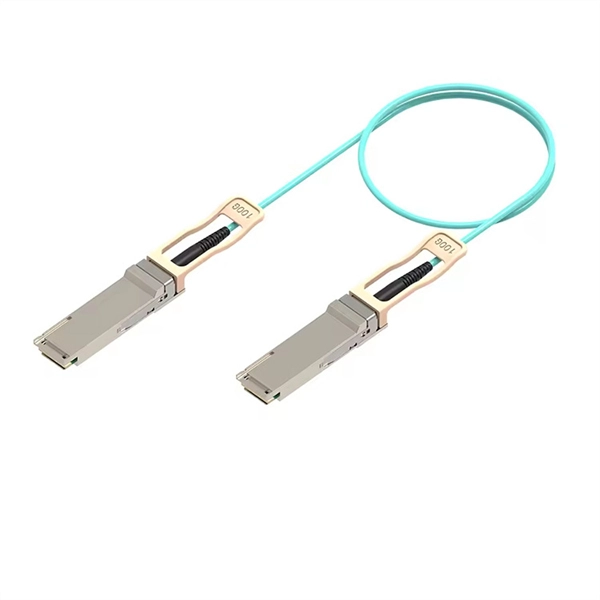
At MWC 2025, Huawei introduced StarryLink optical modules, designed to enhance network experiences with qualities like Stability, Security, and Distance. Describes what an optical module is and FAQs, including the fundamentals, appearance and structure, key performance counters, common types, and naming conventions of optical modules, causes of optical module failures and corresponding protection measures, types of optical modules supported by. In the optical communications field, Huawei focuses on both optical modules and optical chip research, integrating these technologies across the optical communications value chain. Huawei's optical communications products are widely deployed in data centers, metropolitan area networks, long-haul. Optical modules are important devices in fiber optic communication systems. Huawei Optical Module is manufactured by Huawei Technologies Co. and originated in Shenzhen. is a telecommunications network solutions provider. This announcement occurred during the data center session titled. On an optical network, a sender needs to convert electrical signals into optical signals before sending them to a receiver, and the receiver needs to convert received optical signals into electrical signals.
[PDF]
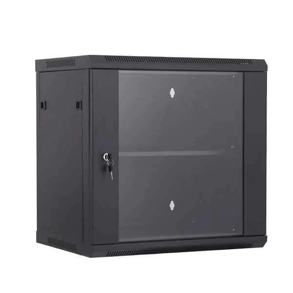
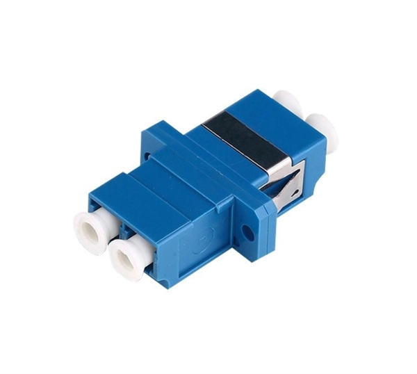
Fiber distribution box, also known as fiber optic distribution frame, is an essential component in fiber optic communication networks. It plays an important role in organizing, managing, and protecting fiber optic cables, ensuring reliable and efficient network operations. They function as junction points that manage, protect, terminate, and distribute fiber optic cables, ensuring efficient data transmission between different. A distribution box serves as a critical component in fiber optic networks. The importance of a distribution box cannot be. In modern optical communication networks, especially FTTH (Fiber to the Home) systems, the fiber distribution box plays a crucial role in ensuring stable, efficient, and reliable signal distribution.
[PDF]

Unlike DSL or cable, which use copper wires, fiber optic Internet service relies on optical fiber to transmit data. These fiber optic cables, made of glass or plastic, use light pulses instead of electrical signals, enabling high-speed Internet with low latency and reliable. The process involves a combination of national infrastructure, local engineering, and property-level setup. In this guide, we'll break down the fiber installation process from start to finish and explain key components such as fiber cabinets, flower pods, ducting, and ONT setup. What Is Fiber Optic. Fiber optic internet represents a significant leap forward in broadband technology, offering speeds and reliability far exceeding traditional cable or DSL connections. Check availability first by contacting your internet service provider or visiting their website—fiber now passes over 76 million. The fiber is connected to an Optical Network Terminal (ONT) inside or outside your home. The ONT converts the light from th e fiber into electrical signals that run via an ethernet cable. This fundamental difference is the key to its superior speed, bandwidth, and reliability. The light signals travel at near the speed of light.
[PDF]
The transmitter takes an electrical input and converts it to an optical output from a laser diode or LED. The light from the transmitter is coupled into the fiber with a connector and is transmitted through the fiber optic cable plant. The signal is produced by a crystal oscillator made from quartz. The quartz keeps the signal on frequency. Two other stages include a driver and a power amplifier. In order to send information, you have to modulate the RF carrier. This usually involves a process known as modulation, where the input signal is combined with a carrier signal to create a new signal that can be. Digital coherent optical systems use advanced digital signal processing and modulation techniques at the transmitter and receiver. Therefore, we begin this chapter by reviewing the fundamentals of digital communications, including principles of modulation, channel modeling, and detection. After. Analog optical transmitters and receivers are designed to meet the evolving needs of high-throughput radio frequency (RF) systems across various industries. AOwave analog optical modules support next-generation analog optical links up to the Ka-band, targeting both terrestrial and space. The essential function of a radio transmitter architecture is taking low-frequency information, the baseband signal, and transferring that information to much higher frequencies by superimposing the baseband signal on a high-frequency carrier, i. This could be done by slowly varying.
[PDF]
In this guide, you will find a chronological description of the fusion splicing process, the principal technical standards, and answers to the real-life questions network engineers and procurement teams may have. 📦 For purchasing, use the RP Photonics Buyer's Guide for fusion splicers. It provides an expert-curated supplier directory, buyer-focused technical background information, and structured selection criteria to support professional procurement decisions. This article explains the principle of fusion. Fusion splicers play a crucial role in the field of optical fibre communications by enabling the permanent bonding of two strands of glass fibre to create a continuous pathway for light to travel through. This process is achieved through precise alignment and fusion of the fibre ends using an. Fusion splicing is the process of fusing or welding two fibers together usually by an electric arc. Fusion splicing is the most widely used method of splicing as it provides for the lowest loss and least reflectance, as well as providing the strongest and most reliable joint between two fibers. Each splicer is equipped with a cleaver and stripper, conveniently includes in a single case. The goal is to align the microscopic glass cores (typically.
[PDF]