Protective systems in electricity delivery networks have a major role to play in the increasing of renewable energy systems, and a broad understanding of their current a future application can aid into better tak.
[PDF]

Common methods of protecting busbars include overcurrent-based interlocking schemes, overcurrent-based differential protection, high-impedance differential protection, and percentage differential protection. Interlocking and overcurrent differential protection can be implemented with any suitable. DEFINITIONS. IV EXECUTIVE. Busbar Differential Protection Definition: Busbar differential protection is a scheme that quickly isolates faults by comparing currents entering and leaving the busbar using Kirchoff's current law. Current Differential Protection: This protection method connects CT secondaries in parallel and. Busbars play an important role in power transmission and distribution. They are employed as a central distribution point for all feeders. The problem is that the busbars. Busbars have typically been left without dedicated protection, from the following reasons: It is a fact that the risk of a short circuit happening on modern metal clad equipment is insignificant, but it cannot be completely dismissed. Nevertheless, the damage resulting from one short circuit may be. 25 kV insulation is required. These heat-shrinkable tubes for straight and bent busbars are extremely flexible, allowing them to be easily positioned on busbars and quickly instal ed using a gas torch or oven. They have a high expan-sion ratio, so each size of tubing fits a range of busbar sizes.
[PDF]
It covers standard codes, wiring practices, and norms for protecting generators, transformers, and lines, and provides detailed information on relay characteristics and crycuit design. The department of Electric Power System (EPS) currently has 20 faculty members, including 7 professors (among which Prof. He Jinghan is an IEEE Fellow) and 10 associate professors. In the last five years, the department has undertaken 10 projects funded by the National Natural Science Foundation of. How many people are using ORCID?. The handbook for protection engineers includes guidelines on protective circuitry, protective relay principles, and testing procedures for switchgear and relays. The training program is developed on interchangeable modules that enable to assemble the. ages &importance on Neutral grounding for overall prote s protective schemes for Transformers, Rotating machines, Bus bars, Feeder Restriking Voltage and Recovery voltages - Restriking Phenomenon, Average, Max. RRRV, Current Chopping and Re istance Switching - B ratings and Specifications: Types. The selected protection principle affects the operating speed of the protection, which has a significant im-pact on the harm caused by short circuits. The faster the protection operates, the smaller the resulting ha-zards, damage and the thermal stress will be. Further, the duration of the voltage.
[PDF]

More specifically, these systems keep tabs on voltage, current, and temperature limits and control the disconnect relay. This allows them to disconnect themselves from the external application in case of malfunction. From a drop of rain to the shining sea, an energy storage system is like the earth's bodies of water (hear us out). In a battery energy storage system (BESS), the energy in the battery cells is like raindrops that combine to form a brook. Made of the combined energy from cells, these brooks combine. Battery energy storage systems (BESSs) investment is expected to grow to $103 billion by 2030. ) Battery systems aren't just designed to serve as local power backups, such as the systems used to power critical facilities (including hospitals and data centers) when the normal. When a 300 MWh battery energy storage system (BESS) in Arizona tripped offline during July's heatwave, operators discovered voltage fluctuations had overwhelmed its protection relays. Could your facility withstand such stress? As global BESS installations surge—projected to reach 1. Protection is necessary when energy and voltages combine from the modules, as well as from the battery racks. Fuses are an efficient. The electrical integration design of a Battery Energy Storage System (BESS) is based on the application scenario and includes various aspects such as DC, high/low voltage distribution, control power distribution, grounding, lightning protection, and safety standards.
[PDF]

A phase-sequence relay monitors phase rotation in three-phase systems, protecting equipment from damage due to incorrect or reversed phase order. It guards a 3-phase device against any potential damage due to sequence change. They are deployed anywhere with a phase-sequence change that can damage the device or circuit. They work like a conventional electric relay. The order of these voltages is typically designated as ABC, where A, B, and C represent the phases. The correct phase sequence is vital for proper functioning and protection of various. Engineers use a Phase Failure Relay, which is additionally known as a Voltage Monitoring Relay (or) a Phase Sequence Relay to avoid costly breakdowns. This small but powerful equipment continuously monitors the state of the three-phase supply & guarantees that motors work only according to safe. A phase sequence relay is a tool that controls the correct sequence of phases in three-phase electrical systems. It is basically a special type of protective device that is used to monitor and control the sequence or order in which the phases of a three-phase power supply are connected. The primary function of a Phase.
[PDF]
This article covers various types of protective relays, such as overcurrent, directional, and differential relays, highlighting their operating characteristics and applications in electrical systems. Different Types of Protective Relays What is a Protective Relay?. Protective relays and devices have been developed over 100 years ago to provide “lastline”of defense for the electrical systems. They are intended to quickly identify a fault and isolate it so the balance of the system continue to run under normal conditions. The selection and applications of. Protective Relay Definition: A protective relay is an automatic device that senses abnormal conditions in electrical circuits and triggers actions to isolate faults. Types of Protective Relays: Protective relays are categorized by their mechanism (electromagnetic, static, mechanical) and function. A protective relay is an intelligent electrical device designed to detect faults in power systems and initiate corrective actions such as tripping a circuit breaker. : 4 The first protective relays were electromagnetic devices, relying on coils operating on moving parts to provide detection of abnormal operating conditions such as. Relion protection and control relays for several application reduce complexity.
[PDF]
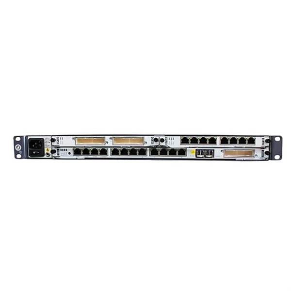
Get Latest Price from the seller Ganesh Electrical - Offering Sifang Relay at Rs 145000 in Gadag, Karnataka. Get Protective Relays at lowest price | ID: 2853527303391. CSC-211 Multifunction Protection IED is selective, reliable and high speed protection IED with rich functions to cover following applications: 1) Protection, bay control unit, MU (Merging Unit), and SCU (Smart control Unit) in one IED; 2) Work as feeder or capacitor bank protection IED; 3) Work as. Copyright © 2020,SIFANG All Right Reserved. Protection relays detect abnormal operating conditions in an industrial system and may trigger an alert or isolate the offending device from the system. The devices can be used for line protection in networks that are grounded, low-resistance grounded, ungrounded, or of a compensated neutral point structure. It is able to supervise. Sifang Relay Install at existing Switch Gear.
[PDF]

Teleprotection is the use of communications for power system protection applications. Underfrequency load shedding (UFLS) is a protection system that senses when frequency is lower than acceptable and directly acts to shed load to correct the frequency drop. For the complete history of this paper, refer to the next page. Published in Sensible Cybersecurity for Power Systems: A Collection of Technical. Abstract: Information on the concepts of protection of ac transmission lines is presented in this guide. Many important issues, such as coordination of settings, operating times, characteristics of. IEEE/IAS/I&CPSD Protection & Coordination WG Chair Jacobs Canada, Calgary, AB rasheek. com IEEE Southern Alberta Section PES/IAS Joint Chapter Technical Seminar - November 2016 Protective Relays - Technical Seminar Nov 2016 - Copyright: IEEE 2 Abstract: Protective relays and devices. Communications in power system protection - Media, topology and protocols (on photo: 110kV-20kV substation protection cabinet; credit: Marko Gostovic via Linkedin) There are a several types of communication media such as micro wave, radio system, fiber optic, etc. The advantages and disadvantages. Communication plays a crucial role in modern protection schemes for power transmission and distribution networks. With the increasing complexity and size of power networks, it has become essential to integrate various elements of the power system, including protective relays, into a unified and.
[PDF]

Review cutout sizes and modules. See specs, datasheets, order online. Vertical Distribution Managers are available in 8” and 12” widths. The VDM offers quick and easy cable routing for high density cable installation. Optional dual front doors offer easy access to cables and provide an elegant look for your data center. Cable fingers and spools support cables as they. Cable entry frames and kits for enclosures, panels simplify routing and strain relief. 91 inches in height and intended for use with 42U relay racks. It is used to organize cables on a relay rack which helps maintain proper airflow. Forward facing and equipped with a hinged front cover, it makes cable access quick and easy. The manager can also be. The M Series has been specifically designed to meet the demanding & varied requirements for protection relay applications in power utility sub-station environments. The standard 4U high 19-inch rack mounting modular configuration simplifies panel design & installation. Mounting points & overall. Weight capacity: 2,000lb. K04. Rackmount Mart - Rackmount Chassis and Rackmount LCD Source. Provide rackmount chassis, rackmount, rackmount lcd, rackmount monitor, kvm switch, disk array, single board computer, industrial computer, mobile rack, server rack, power supply, server case, raid tower, pc case, accessory, cabinet server.
[PDF]
Distance relays, also known as impedance relay, differ in principle from other forms of protection in that their performance is not governed by the magnitude of the current or voltage in the protected circuit but rather on the ratio of these two quantities.OverviewIn, a protective relay is a device designed to trip a when a is detected. The first protective relays were electromagnetic devices, relying on coils operating on moving par. Electromechanical protective relays operate by either, or. Unlike switching type electromechanical with fixed and usually ill-defined operating voltage thresholds. Electromechanical relays can be classified into several different types as follows: "Armature"-type relays have a pivoted lever supported on a hinge or knife-edge pivot, which carries a moving contact. These relays may.
[PDF]

This paper presents a set of newly developed modeling, simulation and testing tools aimed at better understanding the design concept and related applications for protective relaying and substation automation solutions for the smart grid. presentation of protection and control relaying. The report will identify methodology behind these practices, present issues raised by the integration of microprocessor relays and the internal logic and external communication configurations, ying. At Keentel Engineering, we specialize in modeling, simulating, and deploying advanced protective relays to ensure the robustness of medium-voltage (MV) and high-voltage (HV) networks. Our engineering services help utilities, OEMs, and renewable developers simulate real-world contingencies and. This Modern Power System Protective Relaying training course has been designed to provide a clear and perfect understanding of power system protection schemes and devices, including protection relays, fuses, circuit breakers, and other protective devices. In modern power systems, nowadays. To ensure that protective relays, circuit breakers, and other protection devices correctly and selectively isolate faults, minimizing damage to equipment and interruptions to customers while maintaining system stability. One-line diagrams and detailed network data (lines, transformers, buses).
[PDF]
Distance relays, also known as impedance relay, differ in principle from other forms of protection in that their performance is not governed by the magnitude of the current or voltage in the protected circuit but rather on the ratio of these two quantities.OverviewIn, a protective relay is a device designed to trip a when a is detected. The first protective relays were electromagnetic devices, relying on coils operating on moving par. Electromechanical protective relays operate by either, or. Unlike switching type electromechanical with fixed and usually ill-defined operating voltage thresholds. Electromechanical relays can be classified into several different types as follows: "Armature"-type relays have a pivoted lever supported on a hinge or knife-edge pivot, which carries a moving contact. These relays may.
[PDF]

At its core, an overcurrent relay operates on a very simple concept: detect excessive current, then trip fast and isolate the fault. When current surpasses the relay's pickup setting, an internal mechanism triggers the circuit breaker. IEEE/IAS/I&CPSD Protection & Coordination WG Chair Jacobs Canada, Calgary, AB rasheek. com IEEE Southern Alberta Section PES/IAS Joint Chapter Technical Seminar - November 2016 Protective Relays - Technical Seminar Nov 2016 - Copyright: IEEE 2 Abstract: Protective relays and devices. Relay protection against high current was the earliest relay protection mechanism to develop. From this basic method, the graded overcurrent relay protection system, a discriminative short circuit protection, has been formulated. Types of over current relay. It is really current monitoring relay. Overcurrent Relay Definition: An overcurrent relay is a protective device that operates solely based on current without the need for a voltage coil. These relays are known for their speedy operation during a fault and are hence used widely in high-voltage applications. Let's know in. The Art and Science of Protective Relaying, by C. Mason, John Wiley and Sons, 1956. Evaluation of Distribution System Relaying Methods, by A. McConnell, Presented at the Pennsylvania Elec-tric Association, May 16-17, 1957.
[PDF]


