New relay installations require startup and commissioning to ensure proper protection for your system. Our experience in advanced utility and industrial relay applications includes: 1. General inspection of eq.
[PDF]
Examine for any signs of overheating or arcing. Verify that the box is securely mounted and that there are no loose connections. Internal Inspection Open the distribution box and check for dust and debris accumulation. In this inspection article, we will learn about inspecting the main electrical panelboard, from the utility service to the breakers, including common components of the panelboard, and an inspection checklist. Let's begin with InterNACHI's Home Inspection Standards of Practice. Home Inspection. This article series discusses procedures for safe and effective visual inspection of residential electrical systems including electrical panels and other components, when the inspection is conducted by trained building inspection professionals, home inspectors, electrical inspectors, and. In low-voltage electrical systems, LV non-intrusive switchboards control and distribute power. It protects, controls, and monitors building electrical circuits. Non-intrusive means the switchboard can monitor and operate the electrical system without directly interference with the electrical wiring. Use our electrical panel inspection checklist to identify potential issues, ensure routine maintenance, and prevent costly failures of electrical systems. Ensure that all labels and warning signs are legible. This 8-point list covers key areas of your electrical system, helping prevent costly repairs and protecting your property. From electrical panel safety and wiring.
[PDF]
ADSS fiber cables demand site surveys, route planning, and correct mounting hardware. The best practice includes tension checks, buffer tube management, and regular lash-back tests to keep the cable stable. Maintenance includes routine inspections, cleaning, and load checks. These steps help prevent breaks and signal loss. Many engineers trust these methods to ensure stable performance over long spans. All Dielectric Self Supporting (ADSS) Fiber Optic Cable Installation The practices contained herein are designed as a guide. Since there are numerous practices which may be utilized, Prysmian has tested and determined that the practices described herein are effective and efficient. The recommended. Q1: What fiber core counts are available for this ADSS cable? A1: Usually offered in 4, 6, 12, 24, 48 cores, and custom cores can be added as needed. Q2: What fiber type: single-mode or multi-mode? Standards compliance? A2: Generally single-mode fiber complying with ITU-T G. 657. This procedure provides general information for installing all Corning Optical Communications Solo® ADSS All-Dielectric Self-Supporting fiber optic cables from 2-288 fibers. Each installation will be influenced by local conditions. As someone who has worked on numerous ADSS projects at Bright Power Co., Ltd, I've faced challenges ranging from cable sag to high-voltage.
[PDF]
Multimode Fiber Optic Cable Material Selection & Receiving Inspection Checklist Verify that the received materials have been inspected for damage and for compliance to applicable requirements Cable Reel. Multimode Fiber Optic Cable Material Selection & Receiving Inspection Checklist Verify that the received materials have been inspected for damage and for compliance to applicable requirements Cable Reel. In the intricate realm of Fiber Optic Cable Manufacturing, precision and efficiency are paramount. Embracing the use of meticulously crafted forms and checklists offers a transformative advantage. These tools serve as indispensable guides, ensuring systematic adherence to crucial manufacturing. This article is about Multimode Fiber Optic Cable Material Selection & Receiving Inspection Checklist of Outside Plant (OSP) Telecom Distribution System as per International Codes and standards. Cable Reel Storage and Protection is as per Manufacturer's Recommendation. Verify all equipment and. Stranding order, pitch and colors. Core integrity Note: The above QAP is tentative only, vendor may provide their QAP after placement of order and before material delivery. NEIS® are intended to be referenced in contrac documents for electrical construction ation or liability to users of this publication. Existence of a standard shall not preclude any member or nonmember of NECA or FOA from specifying or using.
[PDF]
A beam splitter or beamsplitter is an that splits a beam of into a transmitted and a reflected beam. It is a crucial part of many optical experimental and measurement systems, such as, also finding widespread application in.
[PDF]
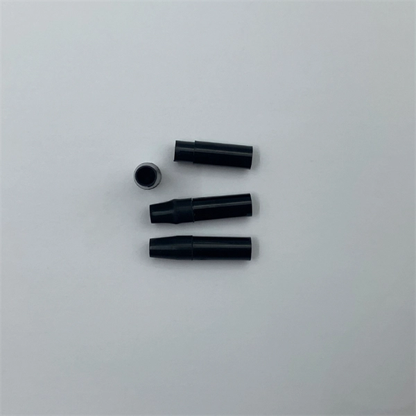
Fiber technicians are taught to keep connections clean after termination, cover connector ferrules and mating adapters with dust caps and clean the ferrule end whenever it is opened to the air. Fiber optic cables are a critical component in modern networks, with their performance directly affecting the stability of data centers and enterprise networks. Effective lifecycle management of fiber optic cables, from selection and installation to daily maintenance and replacement, is essential. That advice is misguided. It could hurt an installer or get them sued by an irate network owner. We've created a simple guide on keeping fiber optic cables in good condition without impairing them. Avoid getting them damaged by handling them with extreme care. We've created a simple guide on maintaining.
[PDF]

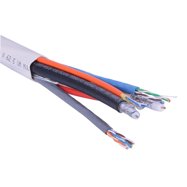
A single strand of glass fiber, called single-mode fiber, is used to transmit single-mode or light beams. It can transmit higher bandwidth than multimode fiber but requires a light source with a limited spectral range. In fiber-optic communication, a single-mode optical fiber, also known as fundamental- or mono-mode, is an optical fiber designed to carry only a single mode of light - the transverse mode. Modes are the possible solutions of the Helmholtz equation for waves, which is obtained by combining. A common type of optical fiber used to transmit over longer distances is single-mode fiber. One of two types of optical fiber, the other is multimode fiber. ” This technology is foundational to modern digital communication, enabling the high-speed transfer of massive amounts of data over vast distances. Generally, single mode cable has a narrow core diameter of 8 to 10µm (micrometers), which can propagate at the wavelength of 1310nm and 1550nm. Modes of light can only propagate through.
[PDF]

Among the essential components in fiber-based networks are fiber optic switches, which help optimize data transmission, network management, and traffic flow. This blog will explore the fundamentals of fiber optic switches, covering types, advantages, and considerations for selecting a model to meet. An SFP (Small Form-factor Pluggable) module is a hot-swappable transceiver used in switches, routers, servers, and telecom equipment to transmit data over fiber or copper connections. Different SFP modules support different: That's why selecting the correct model matters. The first step is. Fiber optic switches are devices used to control the flow of light in fiber optic networks. They are used in a wide range of applications, including telecommunications, data centers, industrial automation, and military and aerospace. The simplest device is an on/off switch with one input and one output, which allows. One of the fundamental choices when selecting a fiber optical switch is the type of fiber used—single-mode fiber or multi-mode fiber. Both have distinct characteristics that impact performance, cost, and application suitability. These connectors serve as the interface between the delicate optical fibers and the active components of the network infrastructure.
[PDF]
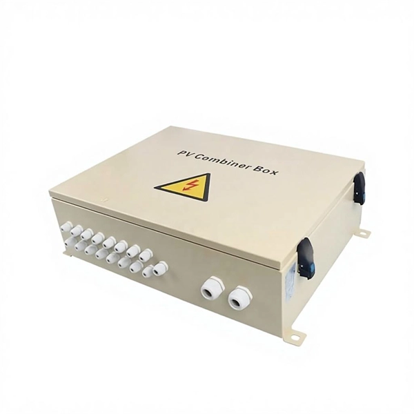
The electrical box is made of 0. 5 mm cold-rolled steel, featuring high toughness, pressure resistance, and rust resistance;The shell has an epoxy polyester powder coating with good mechanical and leveling properties Whether for outdoor installations or indoor electrical. The electrical box is made of 0. These enclosures not only organize complex wiring but also protect sensitive. NAHMA PLC is a premier metal enclosure manufacturer in Ethiopia, specializing in high-quality sheet metal fabrication. We produce durable, standards-compliant enclosures designed to protect sensitive electrical and electronic components in any environment. From standard junction boxes to large. Waterproof and weatherproof junction box for all electronic installation works. Check each product page for other buying options. Price and other details may vary based on product size and color. This junction box has high water resistance up to IP67, high dust resistance, and is suitable for outdoor street light connection, communication wiring, airport, construction, mechanical equipment, outdoor solar equipment and so on. It can. Junction boxes by cape electric are made from halogen free fibre reinforced Polycarbonate (Outdoor) / Polystyrene (Indoor) materials which are available in IP65 Range for Outdoor / Indoor Application. IP68 Ranges of Junction Boxes are used in Extreme application such as underwater or soil.
[PDF]
Coherent optical module refers to a typically hot-pluggable coherent optical transceiver that uses coherent modulation (//) rather than amplitude modulation (RZ//) and is typically used in high-bandwidth data communications applications. typically have an electrical interface on the side that connects to the inside of the system and an optical interface on the side that connects to the outside world through a fiber optic cable. The technical details of coherent op.
[PDF]

A fiber is used to support G. 691 with a maximum rate of STM-16 or 10Gbit/s and a maximum transmission distance of 40 km (Ethernet) and STM-256 for G. This document outlines the specifications for a single-mode optical fiber and cable designed for use around the 1310 nm zero-dispersion wavelength, suitable for both the 1310 nm and 1550 nm regions, and compatible with analogue and digital transmission. It details the fiber's geometrical, optical. G. 652 is an international standard that describes the geometrical, mechanical, and transmission attributes of a single-mode optical fibre and cable, developed by the Standardization Sector of the International Telecommunication Union (ITU-T) that specifies the most popular type of single-mode. G. 652 optical fiber is a kind of optical fiber that is widely used in the network. 652 is mainly based on the requirements of PMD and the attenuation requirements at 1383nm. 652D is the type of optical fiber in the optical cable, which represents non-dispersion-shifted single-mode fiber, and is currently the most widely used single-mode fiber in China. This article will provide a detailed introduction to the structure, characteristics, and applications of standard single-mode fiber. G652 is a specification for optical fiber cables. It is part of the International Telecommunication Union (ITU-T) G.
[PDF]

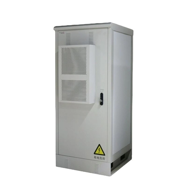
This guide describes the general requirements, functional and technical performance requirements, test requirements, labeling and packaging requirements, transportation and storage requirements, supply integrity requirements, and quality assurance requirements for hybrid high-voltage. This guide describes the general requirements, functional and technical performance requirements, test requirements, labeling and packaging requirements, transportation and storage requirements, supply integrity requirements, and quality assurance requirements for hybrid high-voltage. Guide for Technical Requirements for Hybrid High-Voltage Direct Current Transmission Protection and Control Equipment This guide describes the general requirements, functional and technical performance requirements, test requirements, labeling and packaging requirements, transportation and storage. purpose of this white paper is to aid WECC members (Specifier) in specifying and applying relay systems that will provide adequate protection of extra-high voltage (EHV) on 345-kV or higher transmission lines and comply with the NERC Reliability Standards. The recommendations in this white paper.
[PDF]


