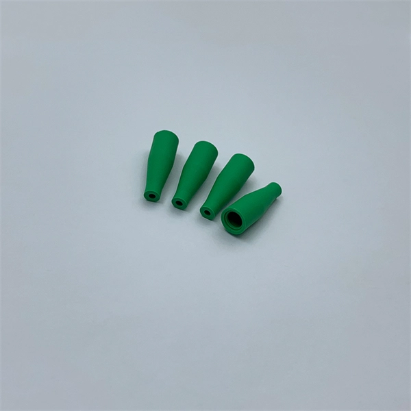
Tilt sensors are devices that measure the tilt or slope of an object with respect to a reference. Fibre Bragg Grating (FBG) tilt sensors are a specific type of tilt sensor that utilizes the principle of Bragg's law in fiber optics to measure tilt angles. The tilt sensor is composed of two cylindrical floats suspended in water, connected with FBG. When the external environment causes the tilting of the sensor. Abstract—A surface-mounted tilt sensor was designed and fabricated to measure the inclination angle of engineered structures or slopes in two directions. In a FBG tilt sensor, the optical fibre is. We demonstrate a new concept for an all-fiber inclinometer based on a tapered fiber Bragg grating (tFBG) in a fiber ring laser (FRL) with the capability of measuring the tilt angle and temperature simultaneously.
[PDF]

Whether you need singlemode, armored, or indoor plenum, this guide gives you the exact cost per foot of fiber optic cable — including installation — so you can budget without guesswork. Data aggregated from Q1 2026 contractor invoices across Texas, Ohio, and North Carolina. Buying fiber optic installation services involves several cost components, with total price influenced by length, location, and access. The main cost drivers include trenching or aerial deployment, materials, labor hours, and any required permits. This guide presents typical price ranges in USD to. Whether you're running fiber to a home or a data center, here's exactly what contractors are charging in 2026. What is the real cost of fiber optic cable per foot in 2026? After analyzing 40+ U. Whether you. Fiber-optic cable materials typically cost $1 to $6 per linear foot, depending on fiber count and cable type. Commercial building installations with 100-200 network drops generally range from $15,000 to $30,000. Single-mode fiber costs less per foot than multimode fiber, but it requires more. Costs for fiber optic cable installation vary by cable type, length, and installation method. The main cost drivers are cable grade (indoor vs outdoor, riser vs plenum), fiber type (single-mode vs multimode), connectorization, and installation length. These elements influence the overall price, making it important to evaluate each project individually to.
[PDF]
A laser diode will always have at least three pins. These three pins are defined as input, output, and case (or ground). Laser diodes (LD) are semiconductor devices that convert electrical energy into high-power optical energy. These devices are currently used in the fields of telecommunications and medicine and in industrial cutting and welding applications. This article discusses the characteristics common to laser. Due to their sensitivity to injected current, laser diodes are typically driven by a stable current source., voltage sources or generic power supplies, are too noisy for most applications and can generate voltage and current fluctuations and transients that may damage the laser. The output power of a diode laser is a function of the operating current. Pout = output power; I = current; th = threshold; T = temperature; j = junction (the place where laser radiation originates in the laser chip); Iop = operating current driving the diode laser. Here is a helpful short video on YouTube explaining constant current and constant voltage sources, and why current sources are preferred for controlling laser diodes. Most of them obtain electrical power from the public grid, but there are also battery-operated devices. Figure 2 shows common power supply and ground configurations where the laser anode is connected directly to the power supply; this is a common configuration for commercially-available laser drivers.
[PDF]
Can two switches with fiber ports be directly connected through fiber ports? The answer is yes. The connection between two or more Ethernet switches in a certain way (Uplink port, etc. ) is. Switch optical port intercommunication means that the optical fiber ports of two switches are connected to each other to achieve the purpose of network connection. Fiber optic technology is widely used in networking due to its high-speed data transmission capabilities and long-distance coverage. SFP transceiver modules almost always require two fiber optic cable strands. Fiber provides: Increased internet signal bandwidth. ) is called the cascade. Traditionally, network switches have been connected using copper cables, but with the increasing demand for high-speed and reliable connectivity, fiber optic cables have gained prominence. This article aims to provide a comprehensive understanding of how network switches are connected to fiber.
[PDF]
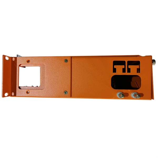
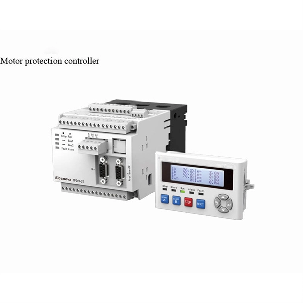
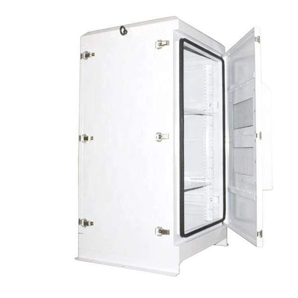
Primary: The main distribution panel, supplies power from the transformer. The terms primary, secondary, and tertiary distribution boxes are relative. Let's make an example for clarity: A newly constructed residential area introduces a 10kV power line to a substation. From the transformer's low-voltage side (0. Spot Networks are used for customers with the highest reliability requirements. This configuration connects two or more transformers (fed from at least two. A complete set of products can form a complete construction electricity three-level protection system, to achieve the purpose of one machine, one gate, one protection. The secondary box is designed with inside and outside doors and sprayed with plastic. Safe and beautiful, waterproof box top. These smaller breaker panels, also known as sub-distribution boards, are commonly used to provide power to secondary circuits within a building. Understanding the components and wiring configuration of an electrical sub panel is essential for safe and efficient electrical installations. In this. ACS takes the basic idea of zone wiring and combines it with pre-cut, pre-tested cable and plug-in connectors, to provide power and telecommunication systems that can be installed under raised floors (The Intelligent Floor), or in accessible ceilings (The Intelligent Ceiling). installed under.
[PDF]
Fiber optic communication relies on transmitting information as pulses of light through thin strands of glass or plastic called optical fibers. Instead of using electrical signals (like in traditional copper wires), it uses electromagnetic radiation in the form of light. This method encodes data into light signals by modulating properties like wavelength, phase, and polarization. The light signals propagate to the receiver through the fiber optic cable. Optical fiber. Okay, let's break down the use of electromagnetic radiation (specifically light) in fiber optic communication. It's a fascinating and crucial technology! Here's a comprehensive explanation, covering the basics, the types of light used, how it works, advantages, and some challenges. The light is a form of carrier wave that is modulated to carry information. This method of data transmission has gained substantial significance in modern communication networks due to its capacity to deliver high-speed internet and other forms of. By using the phenomenon of total internal reflection, light can be transported over long distances without reduction of the energy density due to divergence of the beam. The principle has been known for a long time, but the topic was greatly boosted by the invention of the laser.
[PDF]
Electric power distribution is the final stage in the. Electricity is carried from the to individual consumers. Distribution connect to the transmission system and lower the transmission voltage to medium voltage ranging between 2 and 33 kV with the use of. Primary distribution lines carry this medium voltage power to located.
[PDF]

Global key players of Arrayed Waveguide Grating include NTT, NeoPhotonics, Accelink, Broadex Technologies, Agilecom, etc. The top five players hold a share over 64%. Asia-Pacific is the largest market, and has a share about 48%, followed by North America and Europe. Array waveguide gratings are important in telecommunications because they enable multiplexing and demultiplexing. Function: AWGs are used mainly for multiplexing (DWM). Operating. Arrayed waveguide gratings (AWGs) are passive optical devices based on planar lightwave circuits (PLCs) that spatially separate or combine light of different wavelengths. They utilize a phased array of waveguides with constant path length increments to create constructive interference for specific. Did you know that Arrayed Waveguide Gratings (AWGs) can multiplex and demultiplex over 100 different wavelengths of light on a single optical fiber? This makes them foundational to Dense Wavelength Division Multiplexing (DWDM), a technology that dramatically increases the bandwidth of optical. Arrayed waveguide gratings (AWG) are commonly used as optical (de)multiplexers in wavelength division multiplexed (WDM) systems. These devices are capable of multiplexing many wavelengths into a single optical fiber, thereby increasing the transmission capacity of optical networks considerably. At the transmission end, AWG arrayed. The AWG Arrayed Waveguide Gratings Module Market Size was valued at 799. 2 USD Million in 2024.
[PDF]
It is currently used in modern three-CCD cameras. An optically similar system is used in reverse as a beam-combiner in three- LCD projectors, in which light from three separate monochrome LCD displays is combined into a single full-color image for projection.OverviewA beam splitter or beamsplitter is an that splits a beam of into a transmitted and a reflected beam. It is a crucial part of many optical experimental and measurement systems, such as. In its most common form, a cube, a beam splitter is made from two triangular glass which are glued together at their base using polyester,, or urethane-based adhesives. (Before these synthetic,. Beam splitters are sometimes used to recombine beams of light, as in a. In this case there are two incoming beams, and potentially two outgoing beams. But the amplitudes.
[PDF]

Mainly 9steps: Step 1: cut cable with cutting machines in lengths Step 2: put the connector spare parts on the cable Step 3: Strip cable jacket, coating till bare fiber, and make all parts in ready Step 4: Insert fiber into ferrule, glue dispenser and heat oven Step 5:. Mainly 9steps: Step 1: cut cable with cutting machines in lengths Step 2: put the connector spare parts on the cable Step 3: Strip cable jacket, coating till bare fiber, and make all parts in ready Step 4: Insert fiber into ferrule, glue dispenser and heat oven Step 5:. Learn how to make a fiber optic patch cord step by step, from preparation to testing, for reliable high-performance connections. Most guides on making fiber optic patch cord 1 s feel incomplete. They often focus on the final assembly steps, leaving the foundational stages a mystery. From cable cutting to connector assembly and testing, you will gain valuable insights into the production of. Fiber optic patch cords and Pigtails are very important passive fiber optic components in fiber optic networks. Use the fiber optic cleaver to cut the. This document describes the installation and use of the mode-conditioning patch cords listed in Table 1. A mode-conditioning patch cord is shown in Figure 1 IEEE 802. 3z-compliant optical fiber assembly consisting of a single-mode fiber permanently coupled off-center to a 62. 5-micron multimode.
[PDF]
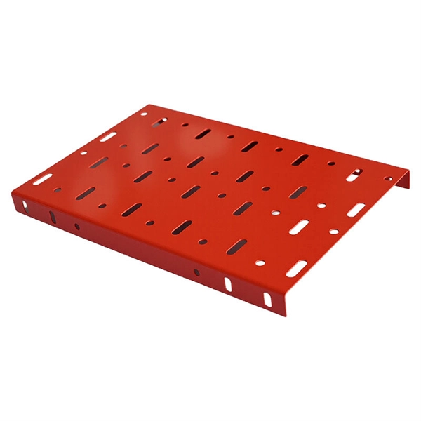
This guide covers the critical steps, from selecting the right electrical cable tray and performing accurate cable fill calculations to managing a safe cable pull through and ensuring all bonding and grounding requirements are met. But before you lay the first tray or clamp down a single cable, you need a solid plan. This guide breaks down the process step by step. Plan the Route Before You Drill No installation should start without a plan. For licensed electricians, mastering these principles is essential. Cable tray installation implies the construction of an electric road that will be safe. In order to get it right, installers are supposed to adhere to a plan that ensures that wires are kept cool and the building is stable. The beginning of success is to review the Bill of Quantities (BOQ) so that. Cable tray systems provide a safe, organized, and flexible method for supporting insulated conductors and cables in commercial and industrial electrical installations. When properly selected and installed, cable trays simplify routing, improve accessibility, and support future expansion while. Proper installation of cables in trays is critical for maintaining an efficient and safe electrical system. This process is integral to determining the optimal arrangement and configuration of cable trays, which are essential for routing and supporting electrical cables within buildings and.
[PDF]

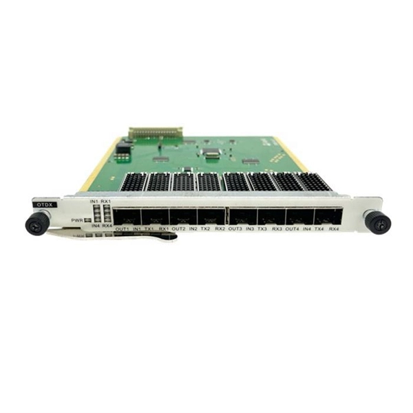
Single fiber modules (BiDi) use one fiber for both transmitting and receiving data. This saves space and money. They are easier to set up and give steady communication. They use a thin fiber. Pioneer LX305 only has 1 optical input, can I add another with some kind of splitter? I love my new receiver but I need a second optical input and I'm wondering what my options are in this regard. Can anyone help? Thanks in advance. Edit: Everyone is going to ask this question, so here are my. The single-mode optical fiber is designed and engineered to carry one single light mode in a minimal core diameter. It is specified as the best for especially long-distance applications than multimode fiber. Due to its. The optical module serves as a crucial component in optical fiber communication systems, operating at the physical layer, which is the lowest layer in the OSI model. Its primary function is to achieve optoelectronic conversion by converting electrical signals into optical signals and vice versa. An. There are single-fiber and dual-fiber optical transceivers. How do we choose, and what are their differences and advantages? Let's learn about this! What is a Single-Fiber (BiDi) Transceiver? Single fiber module also called BiDi transceiver or WDM module.
[PDF]