This chapter presents the development of the Energy Internet throughout the history as an evolutionary solution based on modern technological development and needs, with the respect of its architecture, key features, and key concepts, such as energy router, prosumer, and virtual. This chapter presents the development of the Energy Internet throughout the history as an evolutionary solution based on modern technological development and needs, with the respect of its architecture, key features, and key concepts, such as energy router, prosumer, and virtual. Energy Internet, a futuristic evolution of electricity system, is conceptualized as an energy sharing network. The. ITM University Gwalior, India. coordinating and controlling the many parts of a system, whether they are locally located or geographically dispersed. The study wraps up by outlining the most pressing problems that will need to be solved in order to implement an.
[PDF]
In this comprehensive guide, we delve into the intricacies of fiber optic splicing—encompassing methodologies, instruments, and best practices—while highlighting Dekam Fiber's state-of-the-art offerings that facilitate durable networks. It's the process of joining two fiber optic cables using techniques such as fusion splicing and mechanical splicing, crucial for maintaining uninterrupted communication networks. In this guide, we'll explore what splicing of fiber entails, why it's important, and dive into the key methods and tools. Fiber termination refers to the process of preparing the end of a fiber optic cable to connect to another fiber, a device, or a network. Proper termination is essential for ensuring optimal performance, reducing signal loss, and maintaining the durability of the connection. Unlike using connectors, which are designed for frequent connection and disconnection at patch panels, splicing creates a permanent, stable joint with minimal light loss. What is Fiber Optic Splicing and Why is it Needed? – #1. Use and Maintain Your. Splicing fiber optic cables involves precisely joining two fiber ends to create a continuous optical path. This article explores how to splice fiber, focusing on achieving minimal signal loss and ensuring reliable data transmission through the proper fusion splicing techniques and mechanical.
[PDF]

Calculate horizontal, vertical, or compound cable tray offsets based on bend angle, offset distance, and available installation space. Use this tool to estimate sloped section length, horizontal run requirement, cut marks, and installation feasibility. Click "Calculate" to see the minimum bending radius and the recommended standard tray bend radius (300mm to 900mm) required for safe installation. Tray bend radius must be ≥ minimum cable bend radius. Use the largest cable diameter in the tray for calculation. Always select the next higher standard. Would someone kindly let me know the formula to create a flat 45 in say 100 mm cable tray for example. So I can then use the formula on different cable tray sizes and to different angles. the cable tray is 3 metres in length, this doesnt matter but i think the width does. each bend is a 45 degree angle. but the length of the part in the centre is the concern as i have seen different. The method for producing bridge bend elbows is as follows: Take a 90-degree cable tray bend elbow as an example, and apply the same principles for 45-degree bends accordingly. The length of the bottom side (bottom diagonal) after bending the cable tray should be equal to the width of the cable. How to bend 22. 5 degree of cable tray 3 layer with the same distance and gap • HOW TO BEND 22. 5 DEGREE OF CABLE TRAY 3 LA. Measure this distance along the straight tray.
[PDF]

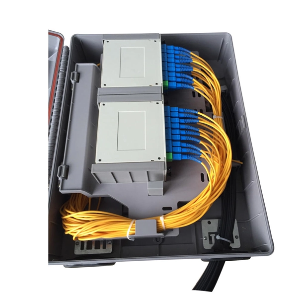
This complete guide explores everything you need to know about ODFs — from their structure, types, and key components, to installation best practices and modern design trends. A fiber optic distribution box, also known as a fiber optic terminal box or termination box, is a device used to connect and manage fiber optic cables within a network. It acts as a central point for terminating, splicing, and distributing these cables, providing necessary protection and. Fiber distribution boxes play a crucial role in network management, providing a centralized and protected access point for optical cables. Distribution boxes are especially essential for FTTH networks, where they enable the efficient connection and management of optical fibers from a central. Fiber distribution boxes represent a critical component in modern telecommunications infrastructure, serving as the connection point between main fiber optic cables and individual subscribers. It is primarily used to terminate, splice, and organize optical fibers, providing a structured cabling solution for in-building and outside plant applications.
[PDF]
Splice Diagrams or Matrices capture an electric or optical network inside a location – documenting cables, ported equipment, and connections. Splices are fiber-to-fiber, port-to-fiber and port-to-port. Fiber optic cable splicing involves joining two fiber optic cables together. Another method of connecting optical fibers is termination or connectorization, which consists of processing the end of a fiber optic bundle so that it can be connected to other fibers or devices through fiber optic. In this guide, we cover the basics of fiber optic splicing, how to perform splicing using two different methods, and finally some best practices to perform good fiber splicing. Ensure Your Splicing Tools are Clean – #2. Use and Maintain Your. What to show on a network diagram? Fiber optic network diagrams represent the architecture and connectivity of fiber optic systems, and their design philosophy integrates technical, functional, and conceptual aspects. The diagrams abstract complex details of fiber optic systems to make them. This Geoschematics drawing remains easy to read despite containing more than 2000 fibers and 500 splices. All students and instructors must wear safety glasses in this lab. It is copyrighted by the FOA and may not be distributed without FOA permission. This VHO covers similar material to the videos on YouTube. The lab manual has several.
[PDF]

This guide covers everything: what fiber optic pigtails are, how they differ from patch cords, which connector and polish type to specify, how to choose between mechanical and fusion splicing, and the real-world applications where pigtails are the right call. In this guide, we cover the basics of fiber optic splicing, how to perform splicing using two different methods, and finally some best practices to perform good fiber splicing. What is Fiber Optic Splicing and Why is it Needed? – #1. Whether you're building out an ODF. Think of a fiber optic cable splice as the seamless stitching that keeps data flowing through the delicate threads of a network—like a master tailor joining fabric with precision. Whether repairing a broken cable or extending a fiber run, fiber optic splicing ensures light signals travel. Fibre optic splicing is an essential skill in the world of modern telecommunications, offering a reliable method to connect optical fibres for seamless data transmission. As the demand for high-speed internet and robust communication networks continues to grow, learning to splice fibre optics is. In this guide, you will find a chronological description of the fusion splicing process, the principal technical standards, and answers to the real-life questions network engineers and procurement teams may have. Therefore, we will also touch on cost factors, risk management, and best practices in.
[PDF]