This video shows real on-site footage of electrical installation, demonstrating safe and standardized wiring methods used by professionals. The National Electrical Code (NEC) Section 700. 10 provides critical guidelines for the wiring of emergency systems. These systems ensure continued operation during power outages, protecting lives and maintaining functionality in key buildings. This guide breaks down the essential requirements of. Emergency system circuits supply power to critical life safety loads such as emergency lighting, fire alarm systems, fire pumps, smoke control systems, and essential communication and control circuits. Correct wiring design for emergency system circuits is essential to maintain power integrity. The general rule in 700. 10 (B) is to keep wiring from an emergency source or emergency source distribution overcurrent device to the emergency loads entirely separate from all other wiring and equipment, unless otherwise permitted in 700. 10 (B) (1) through (5). 12) of the interruption of the normal electrical supply.
[PDF]

Lighting Circuits: Use 1. 5 mm² copper wire. Dedicated Circuits: AC, geysers, and ovens should have 4. Main Incoming Cable: Use 10 mm² or 16 mm² for main supply connections. Also, consider. Professional electrical wire sizing tool based on National Electrical Code (NEC) standards. Calculate proper wire gauge, voltage drop, and ampacity for safe electrical installations. Input your electrical parameters to get accurate wire size. Comprehensive NEC-compliant electrical feeder size charts with copper and aluminum ampacity tables, voltage drop calculations, and real-world installation examples for safe electrical work. Electrical feeder sizing is one of the most critical calculations in any electrical installation, yet it's. This guide gives a clear tech look at home wiring sizes – breaking down what matters without fluff or filler. We'll show you clear, useful info and steps that make sense when setting up your setup. What is House Wiring Cable and Why Does It Matter So Much? Simply put, a house wiring cable is the. Choosing the right wire size is critical for electrical safety and code compliance. Whether you're building a new home, remodeling, or adding circuits, properly sized cables protect against overheating, voltage drop, and fire hazards. Incorrect sizing not.
[PDF]

NEC-compliant grounding wire sizing calculator tool. Please enter a valid service size between 30 and 2000 amperes. The National Electrical Code (NEC) provides clear guidelines for ground wire sizing through Table 250. 122, but understanding how to apply these requirements correctly can make the difference between a safe installation and a costly code violation. Proper grounding conductor sizing is critical for. Calculate proper grounding wire sizes based on electrical system parameters. By fault current and length — considers potential short-circuit currents and conductor distance. By breaker size — quick lookup based on the installed breaker. NEC Ground Wire Size Chart provides standard wire sizing for grounding conductors in electrical systems. This chart is used to size the ground wire that runs with branch circuits and feeders. The second is the Grounding. AFL AlumaCore OPGW (Optical Ground Wire) is preferred for its central aluminum pipe and color-coded fiber optic buffer tubes which simplify the splicing process while providing optimum fiber protection as well as long term product reliability. Optical Ground Wire (OPGW) is a dual functioning cable.
[PDF]

In this video, we'll show you how to connect an energy meter to a distribution board (DB) safely and efficiently. A residential electric meter box wiring diagram illustrates the connection between the utility service drop and the main breaker panel. It shows the hot wire entering the meter lugs, the neutral wire connecting to the neutral bus bar, and the essential ground wire linkage to ensure system safety. energy meter connection with distribution box How to Connect an Energy Meter to Your Distribution Box Easily Steps to Properly Connect Your Energy Meter to a Distribution Box. This prevents arc faults and ensures safety when modifying or inspecting current paths. Inside the service housing, line conductors from the utility feed typically enter through the. The wiring that links the utility company's service point to a home's electrical distribution system is the main service connection. This “meter to panel” wiring establishes the pathway for all incoming electrical power from the grid to the home. Whether you're an electrician or a DIY enthusiast, this guide will help you understand the basics of home electrical distribution. What is Distribution Board? Distribution board.
[PDF]
This guide summarizes field-proven rules for AI/AO/DI/DO wiring, shows how to choose between NO/NC contacts under the fail-safe principle, and explains how to decode typical cable schedule entries. Instrument installation with the associated cable installation/electrical signal and control wiring should be carried out by skilled personnel who are acquainted with the safety requirements and regulations for the plant site for that specific project. Generally instrument cabling is usually run in. Few factors are to be considered or taken care of while wiring a field instrument to control panel. Based on noise susceptibility limits (NSL) according to IEEE 815 standard, various field instrument signals are classified as below. Noise Susceptibility Limit Grounding of the signal cable Type of cable Cable Terminations Based on noise susceptibility limits (NSL). Note how the hoop-shaped “jumper” wires are all cut to (nearly) the same length, and how each of the wire labels is oriented such that the printing is easy to read: This next photograph shows a great way to terminate multi-conductor signal cable to terminal blocks. Each of the pairs was twisted. A well-designed and properly installed instrument junction box is crucial for the efficient operation and maintenance of electrical systems. Level 1: High to medium susceptibility Level 2: Low susceptibility.
[PDF]

This video shows real on-site footage of electrical installation, demonstrating safe and standardized wiring methods used by professionals. more Learn how to wire a distribution box step by step!. Plastic is lighter and good for indoor setups. Choose based on where you'll install the box. Inside the box, you'll find things like circuit breakers, busbars, terminal blocks, and wires. These parts control and distribute the electricity to different circuits safely. Some boxes also include DIN. Strictly speaking, the word “Distribution Box (D-box)” can refer to two categories: electrical distribution boxes and septic tank distribution boxes. This article mainly talks about the first one. I'll cover these four popular conduits: Remember, electrical conduits can be either rigid or flexible, and they come in various materials like metal, aluminum. NEC Article 314 establishes requirements for the installation and use of electrical boxes, conduit bodies, fittings, and handhole enclosures. A conduit body is a removable-cover section of a conduit system that provides access at junctions or termination points. Article 314 applies to: These. Where metal boxes or conduit bodies are installed with messenger-supported wiring, open wiring on insulators, or concealed knob-and-tube wiring, conductors shall enter through insulating bushings or, in dry locations, through flexible tubing extending from the last insulating support to not less.
[PDF]

If you use single pole MCBs then connect only phase wire from the output of the RCCB to the inputs of the single pole load MCB. Connect the earth wire to the earth link. A distribution board or distribution box is where the main power supply is distributed to multiple loads. And all the switching and protective devices are installed in the distribution box. Single Phase Distribution Box generally consists of Double Pole MCBs, Single Pole MCBs, and RCCBs. Learn how to wire a distribution box step by step! This video shows real on-site footage of electrical installation, demonstrating safe and standardized wiring methods used by professionals. Arrangement order: The circuit breakers should be arranged from left to right, and the reserved position is generally placed on the right side of the distribution box. Wire color: The neutral wire is blue, and the color of the phase wire (A phase is yellow, B phase is green, and C phase is red). In this video, we'll walk you through the process of wiring a home distribution box with a detailed connection diagram. Whether you're an electrician or a DIY enthusiast, this guide will help you understand the basics of home electrical distribution. What is Distribution Board? Distribution board. An electrical panel box, also known as a breaker box or a distribution board, is a crucial component of any electrical system.
[PDF]
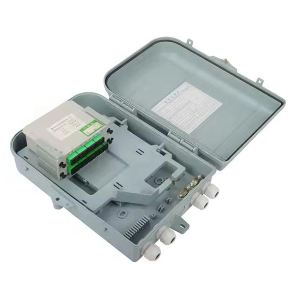
This video shows real on-site footage of electrical installation, demonstrating safe and standardized wiring methods used by professionals. more Learn how to wire a distribution box step by step! This video shows real on-site footage of. Material preparation: Prepare the required circuit breakers, wires, wiring ties and other materials, and ensure that they meet the design drawings and installation requirements. Location determination: Determine the installation position of the circuit breaker according to the position of the. Learn how to install a distribution box safely and correctly. Covers wiring, placement, standards, and expert tips for a compliant setup. A distribution box is the heart of any electrical system. It takes the incoming power and safely distributes it to different circuits throughout your building. It serves as a central hub for distributing electricity throughout a building, ensuring that power is delivered safely and efficiently to all the required locations. This video highlights the installation process for CANTEX Exposed Weatherproof PVC electrical boxes. When an electrical connection is needed outside of a home, commercial or industrial building---or anywhere it might be exposed to the elements, weatherproof electrical boxes and covers are required. It has three categories: residential, commercial and industrial electrical distribution boxes, all of which play important roles in their respective electrical.
[PDF]
When designing a cable tray wiring system, the designer should evaluate the National Electrical Code's (NEC) Equipment Grounding Conductor (EGC) options that are applicable for the project. Use the cable tray as the EGC. The metal in cable trays may be used as the EGC as per the limitations. Cable tray grounding wire is the safety connection that links your electrical system's cable tray to the ground. This provides a safe path for any stray electrical currents to flow safely into the earth, avoiding damage to your equipment and reducing the risk of electric shocks. It involves connecting cable trays to the facility's grounding system, providing a low-impedance path for fault currents and protecting personnel.
[PDF]

Wiring Direction: Wiring between the main circuit breaker and each branch circuit breaker in the box generally goes on the left, and the wiring out of the distribution box generally goes on the right. Binding Requirements: The wires should be bound with plastic. Connection method: Each switch takes a wire from the incoming point and connects it to the incoming end of the switch, or uses parallel connection to reduce the difficulty of wiring. A subpanel is essentially a satellite distribution point that feeds power to. A distribution board, also known as a DB box, is like the central hub of an electrical system. It contains multiple circuit breakers and connects various electrical circuits to ensure the safe flow of electricity throughout the building. Unlike single-phase systems, where power is distributed using. Circuit breaker wiring configurations involve organizing main switches, busbars, and branch breakers within a distribution box. Proper setups ensure balanced electrical loads, ground fault protection, and easy maintenance. Common configurations include single-phase for homes and three-phase for. nt, and/or other requirements. Said drawings are a part of these specifications and are equally important sh 2” and “OMH-3 sh2. ” Strict adherence to ons for manholes are critical. The maximum throat all en setting manholes. Proper slings and attachments are vital t the integrity of the manhole. EFFECTIVE DATE. APPLICATION FOR.
[PDF]
This phenomenon is known as the skin effect. The result is higher electrical resistance, energy loss, and reduced efficiency — particularly problematic for data transmission and high-frequency power applications. Through smart conductor stranding, manufacturers can reduce the. Defective products and waste products of bundled wire and stranded wire, the main problems are over-twisting, inner or outer single wire breakage, lack of strands, single wire or stranded wire surface abrasion, single wire dorsal strand, single wire peeling, scarring, brittle breakage, arching. This phenomenon is known as the skin effect. Through smart conductor stranding, manufacturers can reduce the impact of this effect. Causes of generation. Causes of. Understanding the diverse factors that can compromise cables—mechanical stress, environmental conditions, electrical anomalies, and more—empowers us to prevent, identify, and address issues promptly. By recognizing the importance of cables and the potential risks they face, we can ensure the. Both shielded and unshielded twisted-pair copper cable comes in either stranded or solid wire versions. There are plenty of considerations when it comes to choosing one or the other, including standards, environment, application, and cost.
[PDF]
A junction box contains four trade size 3 raceways: two on the left side, one on the right side, and one on the bottom. Once conductors have to turn, be pulled through, or be spliced inside an enclosure, the box dimensions start affecting installation time, conductor damage risk, and inspection results. A raceway design that looks fine in a panel schedule can still become a problem if the box is too short for an. Pull boxes, junction boxes, and conduit bodies must be sized to allow conductors 4 AWG and larger to be installed without damage to the conductor insulation. The NEC provides sizing requirements in 314. The distance between raceway entries enclosing the same conductor must be at least 6 times the trade. To size a junction box correctly, first decide whether NEC 314. Use box-fill rules for splices and devices, and pull-box rules for large conductors and raceways. The most common mistake is using the wrong. NEC 314. 28 specifies the minimum size requirements for pull and junction boxes in electrical installations. Proper sizing ensures conductors can be installed without damage and allows for proper bending space. How Does the Calculator Work? The calculator uses NEC 314. Minimum Length = 8 × Largest Conduit Size Minimum Dimension = 6 × Largest +.
[PDF]
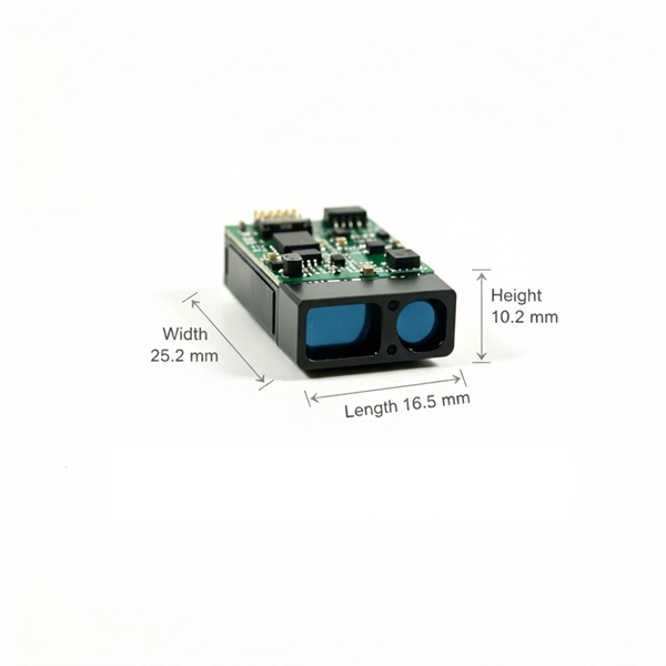
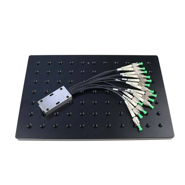
In this guide, we'll break down the essentials, explore different wiring configurations, and provide you with practical tips to get your sensors up and running smoothly. So, grab your tools, and let's get started! Before we jump into wiring diagrams, let's quickly recap what fiber optic sensors are. working principle: Fiber optic sensors use the propagation characteristics of light to detect or measure various physical and chemical quantities. Here are some basic working principles of fiber optic sensors: Propagation of Light: An optical fiber consists of two parts: a core (the central part of. A Fiber Sensor is a type of Photoelectric Sensor that enables detection of objects in narrow locations by transmitting light from a Fiber Amplifier Unit with a Fiber Unit. Detection in Narrow Locations The small sensing section and flexible Fiber Unit cable enable a Fiber Sensor to. Click to download the ODiSI Fiber Optic Sensor Installation Guide. The following instructional videos explain how to install, configure, and calibrate the FiberPatrol FP400 fiber optic fence-mounted intrusion detection sensor. Copyright © 2026 Senstar Corporation. Legal | Accessibility. Surprisingly Stable Detection with Your Finger tip. Exceptionally easy operation and stabilizing technology reduce maintenance cost. If you Login / Signup, you can download the PDF of the Manual. Please note some product models not sold in Singapore may be included in the following manual (s) for.
[PDF]