Precision begins with a quality optical encoder disc in the automation, robotics, and motion control systems of today. This tiny yet essential device transforms physical movement into exact digital signals that dictate speed, position, and direction. What constitutes an optical transceiver? An optical transceiver, a crucial device utilized in optical communication, is an optoelectronic element, allowing the interconversion of optical and electrical signals during the information transmission. It generally has the components for transmission. Therefore, NASA is developing optical communications to address limitations of radio frequency (RF) communications, including: bandwidth, spectrum and overall size of frequency packages and power used. Optical spectrum uses light as a means of transmitting information via lasers. Optical. Optical transceivers are devices that convert electrical signals into optical signals and vice versa, playing a key role in supporting modern high-speed communication networks. They are widely used in data centers and communication systems to enable high-speed, efficient transmission of large. Optical transceiver modules are designed and built by a variety of manufacturers. In the design of optical transceivers, the selection of channel configuration and modulation.
[PDF]
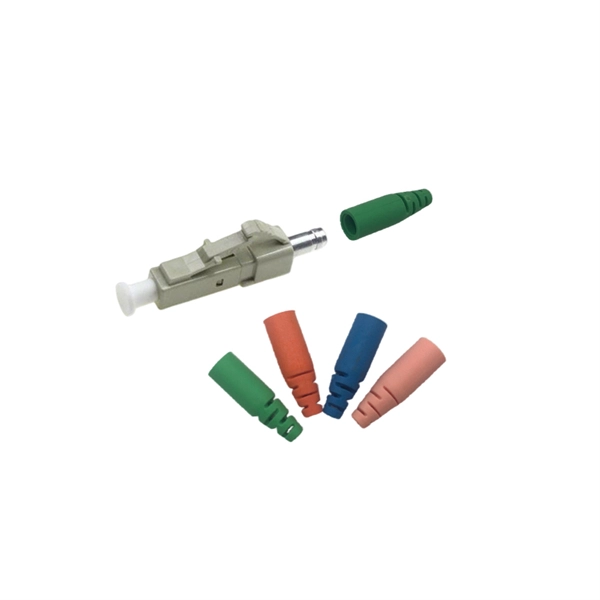
Splice Diagrams or Matrices capture an electric or optical network inside a location – documenting cables, ported equipment, and connections. Splices are fiber-to-fiber, port-to-fiber and port-to-port. Fiber optic cable splicing involves joining two fiber optic cables together. Another method of connecting optical fibers is termination or connectorization, which consists of processing the end of a fiber optic bundle so that it can be connected to other fibers or devices through fiber optic. In this guide, we cover the basics of fiber optic splicing, how to perform splicing using two different methods, and finally some best practices to perform good fiber splicing. Ensure Your Splicing Tools are Clean – #2. Use and Maintain Your. What to show on a network diagram? Fiber optic network diagrams represent the architecture and connectivity of fiber optic systems, and their design philosophy integrates technical, functional, and conceptual aspects. The diagrams abstract complex details of fiber optic systems to make them. This Geoschematics drawing remains easy to read despite containing more than 2000 fibers and 500 splices. All students and instructors must wear safety glasses in this lab. It is copyrighted by the FOA and may not be distributed without FOA permission. This VHO covers similar material to the videos on YouTube. The lab manual has several.
[PDF]

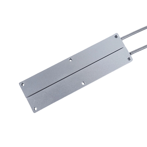
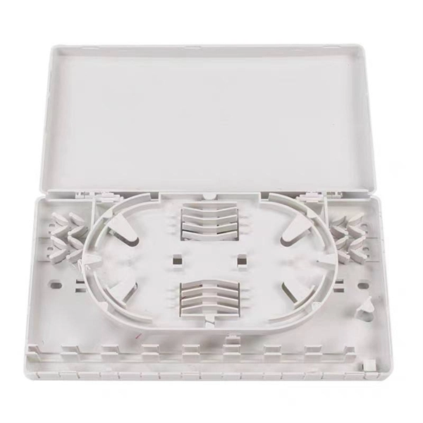
Fiber optic terminal boxes provide functions such as input, branching and splicing of optical fiber cables. Through the connectors and splicing boxes in the terminal box, optical fibers can be quickly connected and repaired. Serving as a critical connection point, FTB facilitates the termination, splicing, or connection of fibers from various cables to other network devices such as switches, routers, or Optical Network Terminals (ONTs). It aids in splicing, splitting, storing, and managing fibers within the appropriate. The optical fiber terminal box is the terminal joint of an optical cable, one end of which is an optical cable, and the other end is a pigtail, which is equivalent to a device that splits an optical cable into a single optical fiber. A fiber pigtail is a specific hardware connection used for cable termination. It is a small enclosure that can house and protect the fiber optic cables, splices, and connectors. The optical fiber termination box and optical fiber splice box serve distinct purposes and are not interchangeable.
[PDF]

from outside the US. EMEA Specific: +49 (0) 228 7489 201 HCS and GiHCS are registered tradema time without notice. This document is for informational purposes only and is not intended to modify or supplement any OFS warranties or specifications relating to any of its. from outside the US. STFOC uses our patented cable jacket construction designed to protect the fiber in the harsh subsea environment. Non-KinkTMSTFOC has a patented design to protect. CommScope bundles hybrid cabling to your custom specifications, using our high-performance fiber-optic, unshielded twisted pair and coaxial cables. Devices deployed at the network edge—a 5G radio, a security camera, or an industrial sensor—require high-speed data connectivity and power. It is technically possible to have a separate fiber and electrical cable, but it adds complexity, cost, and maintenance overhead. Optical hybrid cables address. challenge—OCC has what you need. Our team will make sure the configuration is tailored to your needs and will provide a detailed quote. Email us using the Request a Quote below, or give our team a call. Drive, Avon, CT 0600 erat ing Bend Radiu erat ing Bend Radius Cons from outside the US. Teledyne ODI ofers a comprehensive line of fiber optic and electro/optic hybrid wet mate interconnect products. Wet mate connectors are available in ROV Mate, Stab Mate and Manual Mate configurati sm.
[PDF]
The SFP-1040-WB is a BiDirectional single fiber strand 10G SFP+ optical module using Tx:1330nm and Rx:1270nm wavelengths. The transceiver supports all 10G rated speeds for Ethernet, SONET, SDH or Fibre Channel networks. SFP-1040-WB must be paired with the SFP-1040-WA model to have an operational. The SFP-1040-Wx series single mode transceiver is small form factor pluggable module for duplex optical data communications such as 10GBASE-ER/EW defined by IEEE 802. It has the SFP+ 20-pin connector to allow hot plug capability. All modules satisfy class I laser safety requirements. Digital diagnostics functions are available via a 2-wire serial. The SFP-1040-Dxx is a DWDM 10G SFP+ optical module. It is available for all 45 DWDM 100GHz ITU grid wavelength channels. The transmitter section uses a 1550nm EML, which is class 1 laser compli Rate Select 0, optionally controls SFP+ module recei e Select 1, optionally controls SFP+ module.
[PDF]
A photonic integrated circuit (PIC) or integrated optical circuit is a microchip containing two or more photonic components that form a functioning circuit. This technology detects, generates, transports, and processes light. Photonic integrated circuits use photons (or particles of light) as. architecture and performance of several generations of InP-based PICs. Increased complexity in chip functionality has resulted in a need for increased fabricati n complexity from III-V epitaxy, through wafer fab, die fab, and test. Through continuous learning and improvement, Infinera has. Photonic integrated circuits (PICs) use light (photons) to transmit information, whereas traditional integrated circuits use electricity (electrons), enabling faster signal propagation. Whereas an electronic integrated circuit.
[PDF]
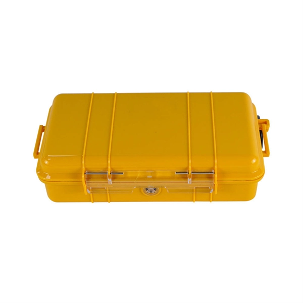
Optical cable junction boxes play a crucial role in connecting and protecting optical fibers, directly influencing the quality and lifespan of optical cable routes. Optical cable splice boxes protect the splicing parts of optical fibers from various hazards, such as water seepage due to adverse. Optical cable junction boxes play a crucial role in managing and organizing fiber optic networks. It serves as a termination point for fiber optic cables, providing protection and distribution of the optical fibers while ensuring efficient signal transmission. Utilizing an optical junction box can significantly enhance your. Optical cable splice box is a popular name, its scientific name is optical cable splicing box, also known as optical cable splicing package, optical cable splicing package and gun barrel. These boxes are designed to house and protect fiber optic splices and terminations, ensuring that the delicate fibers are safeguarded from.
[PDF]
BiDi SFP+ changes the geometry: each module uses a single fiber pair directionally separated by wavelength, so you can run one strand where you previously needed two. One of the most common decisions network engineers face is selecting between single fiber SFP and dual fiber SFP modules. This comprehensive guide explores the differences between single and dual fiber SFPs, their respective benefits, limitations, and use cases—helping you make an informed choice. A single fiber SFP, also known as a BiDi SFP, is designed precisely for this purpose—enabling bidirectional data transmission over a single strand of optical fiber. Unlike traditional SFP transceivers that require two fibers—one for transmitting and one for receiving—a single fiber SFP uses. SFP (Small Form-factor Pluggable) is a compact, hot-pluggable network interface module used to connect network devices (switches, routers, firewalls) to fiber optic or copper cables. An SFP interface on networking hardware is a modular slot for a media-specific transceiver, such as for a fiber-optic cable or a copper. Both transmitting and receiving need one optical fiber to connect. Simplex SFP modules, also known as BIDI transceiver, employs a unidirectional transmission mechanism and have only one port. In practice, that means fewer splice points, smaller patch panels, and less conduit congestion—especially in retrofit buildings.
[PDF]
Cable TypePrice Range (USD/meter)Simplex / Duplex Indoor Cable$0. 30Single-mode Outdoor Cable$0. 50Multimode (OM1/OM2/OM3)$0. 60Armored Cable (Steel Tape / FRP)$0. 50 These are indicative prices. Buyers typically pay for fiber optic cable by length, fiber type, and installation complexity. Main cost drivers include cable grade (indoor vs outdoor, armoured), distance, and labor for trenching, splicing, and termination. Data aggregated from Q1 2026 contractor invoices across Texas, Ohio, and North Carolina. Cost per foot of fiber. How Much Does Fiber Optic Installation Cost Per Foot? Cable Material Costs: Installation Costs by Method: Prices can range from $1 to $50+ per linear foot depending on the method and complexity. The initial cost of installing fiber optic cables can vary depending on the chosen installation method. Cable installation price refers to the total cost of deploying fibre or copper cabling across a site. It includes labour, materials, termination methods, routing complexity, and any environmental factors such as trenching or conduit work. When you plan a structured cabling project, the cost of. Because the core is wider and harder to manufacture to 2025 standards, it's a jump in price: $1. Armored cables: If there's any chance of a shovel or a rat hitting that line, you need steel tape armor. That “insurance” That 'insurance' bumps the price to $1. 50 per meter, depending on several variables.
[PDF]
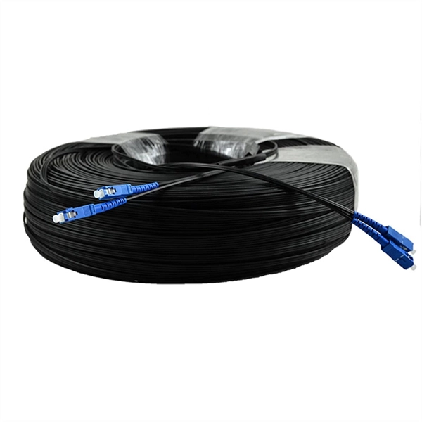
The fiber cores of GYTC8S53 fiber cable is from 2 cores to 288 cores GYTC8S53 is a self-supporting fiber optical cable for outdoor use. Commonly referred to as figure 8 cable, figure 8 fiber cable, figure 8 aerial cable, self-supporting figure 8 cable, or simply figure 8 optical cable, this ingenious structure combines optical fibers with an integrated messenger wire in a distinctive “8” cross-section. This self-supporting design. Hunan GL Technology Co., Ltd Supply 2-144 Cores GYFTC8S Aerial Stranded Figure 8 Fiber Optic Cable With Factory Price, Support OEM, All the figure 8 cables supplied from GL FIBER are complied with IEC 60794-4、 IEC 60793、TIA/EIA 598 A standards. In the GYFTC8S cable, single-mode/multimode fibers are. GYTC8Y is a typical self supporting outdoor fiber optic cable with features of moisture resistance and crush resistance suitable for aerial application. The stranded wires as the supporting part are completed with a polyethylene (PE) sheath to be figure 8 structure. After being coated with steel tape longitudinally, a layer of PE inner sheath is extruded, and then a single layer or double layer thin round steel tape armor is longitudinally wrapped After installation, the. l fibers in loose tubes filled with interstitial gel. Aluminum moisture barr er tape or steel tape armoring options are availa le. A steel messenger wire provides tensile strength. It can work at the temperature from -10 to +70℃.
[PDF]
An optical line termination (OLT), also called an optical line terminal, is a device which serves as the service provider endpoint of a passive optical network. It provides two main functions: to perform conversion between the electrical signals used by the service provider's equipment and the fiber optic signals used by the passive optical network.to coordinate the multiplexing between the conversion. FeaturesOLTs include the following features: • A downstream frame processing means for receiving and churning an cell to generate a downstream frame, and converting a parallel dat. Most vendors integrate an entire fiber optic management system for ISPs to manage OLTs as well as client ONTs and as such are not interoperable. • • BT-PON.
[PDF]
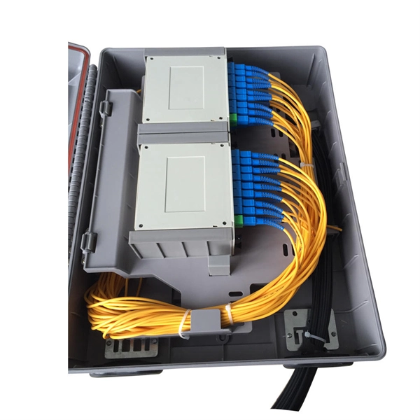
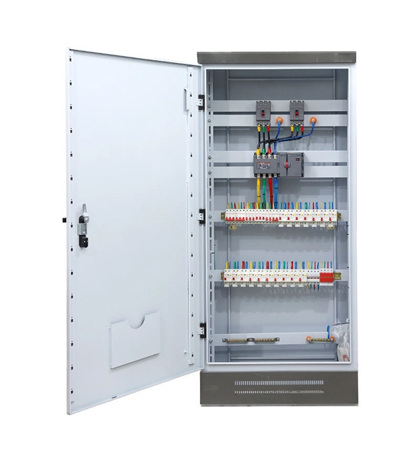
A distribution box, also known as a fiber distribution hub or optical distribution box, is a larger enclosure designed to manage and distribute fiber optic cables to multiple endpoints. It serves as a central point for connecting and organizing numerous fiber optic. Although all three are related to fiber connection and management, their installation locations, functional roles, and positions within the network architecture are fundamentally different. Confusing these devices may lead to non-standard cabling at best, and serious challenges in network. In modern FTTH (Fiber to the Home) and optical communication networks, three types of fiber distribution products are widely used: Splitter Distribution Box, ODF (Optical Distribution Frame), and Fiber Terminal Box. The functions of the four connectors can be. First, let us learn the common point among ODF, fibre optic termination box and fiber optical distribution box, actually, they have similar function, we sort out them as following 4 aspects: 1. fiber termination and optical signal splitting 4. What is the difference between these fiber boxes.
[PDF]
It provides a general plan for spectrum use and the basic structure to ensure efficient use of the spectrum and the prevention of radio frequency interference between services. Learn about the market conditions, opportunities, regulations, and business conditions in tajikistan, prepared by at U. Embassies worldwide by Commerce Department, State Department and other U. agencies' professionals Information and Communication Technologies (ICT) Tajikistan's ICT sector is. Satellite Internet Market Growth The global satellite internet market is experiencing steady growth, driven by increasing demand for reliable connectivity in remote and underserved areas. Through use of the table, manufacturers will have a guide to where in the spectrum to design and build equipment, and. Ministry of communications of Republic of Tajikistan We have an excellent working relationship with the Tajikistan Telecom Wireless Regulatory Authority, officials at Ministry of communications of Republic of Tajikistan. This means that we can ensure all your applications for Wireless Regulatory. On 7 April 2025, in Dushanbe (Tajikistan), Intersputnik, at the invitation of the Communication Service under the Government of the Republic of Tajikistan, attended the International Forum “Digital Transformation: Prospects and Solutions”. Intersputnik Director General Ksenia Drozdova held a.
[PDF]