This chapter presents the development of the Energy Internet throughout the history as an evolutionary solution based on modern technological development and needs, with the respect of its architecture, key features, and key concepts, such as energy router, prosumer, and virtual. This chapter presents the development of the Energy Internet throughout the history as an evolutionary solution based on modern technological development and needs, with the respect of its architecture, key features, and key concepts, such as energy router, prosumer, and virtual. Energy Internet, a futuristic evolution of electricity system, is conceptualized as an energy sharing network. The. ITM University Gwalior, India. coordinating and controlling the many parts of a system, whether they are locally located or geographically dispersed. The study wraps up by outlining the most pressing problems that will need to be solved in order to implement an.
[PDF]

The IEEE standard for protection relays refers to a collection of guidelines developed by the Institute of Electrical and Electronics Engineers. These standards define the performance, accuracy, reliability, and testing requirements of protective relays used in electrical systems. Relay systems protect high-voltage equipment and transmission lines to ensure safe, stable systems. Although failure of a protective relay system may have severe local or regional impacts, most protective relay systems are not required to operate to prove they are in working order. Many of the protective relay systems are seldom called upon to work and have little means of proving they. The testing and verification of relay protection devices can be divided into four groups: Type tests are needed to prove that a protection relay meets the claimed specification and follows all relevant standards. Since the basic function of a protection relay is to correctly function under abnormal. Protective relays are decision-making elements in the protection scheme for electrical power systems. A strong test and maintenance program will keep protective relays in a high state of readiness and help utilities avoid equipment damage and prolonged downtime. This guide provides recommended. This utility standard establishes the requirements for testing and maintaining protection systems, automatic reclosing, and sudden pressure relaying.
[PDF]
This standard has been prepared by the Technical Committee CTN 212 Telecommunication cables and optical fibre the Secretariat of which is held by FACEL. Este documento ha sido adquirido por a través de la suscripción a AENORmás Premium. Para uso en red interna se requiere de autorización previa de. The FOA Online Reference Guide on the FOA website is probably the largest and most used reference site on fiber optics on the Internet. For those who prefer printed. ITU-T handbooks provide information on topics in telecommunications such as operational aspects, network planning, quality of service, implementation guidelines, outside plant protection against electromagnetic effects, measurement methods, security and mobile systems. The Handbook is intended as a. Major International Standards Organizations for Fiber Optics Several international organizations develop and maintain standards for fiber optic products. These standards ensure interoperability across manufacturers, regions, and applications. This work materialized through the development of good practices, procedures and specifications documents, reflecting a certain state of the art at a given time, and the result of a consensus of all stakeholders (op lable.
[PDF]

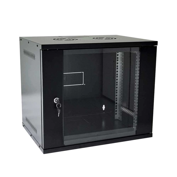
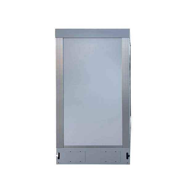
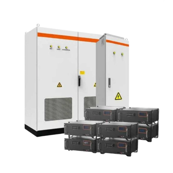
Data center rack enclosures must be 48U to maximize horizontal space. The preferred width is 24 inches with vendor neutral mounting rails that are fully adjustable and compatible with all EIA-310 Electrical Industry Alliance Standards compliant with 19” wide equipment. • Extended battery module increases runtime by hours. • PowerPass Distribution Module allows a step-down voltage to 120V to accommodate a variety of IT equipment. The PPDM also provides a maintenance bypass, which allows you to service or replace the entire UPS without powering down IT equipment. •. Proper installation of components in a data center server rack is crucial for optimal performance, efficient maintenance, and long-term reliability of your IT infrastructure. This guide provides detailed instructions and best practices for setting up various components in your data center racks. The purpose of the Data Center and Server Room Standards is to describe the minimum requirements for designing, installing, securing, monitoring, maintaining, protecting, and decommissioning a data center or server room at the University of Kansas. Choosing the right server rack involves understanding dimensions, weight capacity, cooling needs, and the type of rack, whether open or closed frame. Regular. There are three primary rack types - open-frame racks, enclosed cabinets, and wall-mount racks, each suited for different levels of security, cooling, and equipment density.
[PDF]
Nearly half of Uzbekistan's population of 36.4 million is concentrated in Tashkent and the Fergana Valley, the two regions that consumer product manufacturers should consider as the most promising entry poin.
[PDF]

Protective relays are essential devices used in electrical power systems to detect faults and abnormal conditions, initiating corrective actions to prevent equipment damage and ensure system stability. These relays play a crucial role in the protection of transformers, generators, transmission. A protective relay is an intelligent device that senses abnormal electrical conditions, such as overcurrent, under-voltage, or frequency deviations. It initiates the operation of circuit breakers to isolate the affected section. This prevents damage to equipment, reduces downtime, and safeguards. Protective relays are critical components in power systems, providing essential protection for various elements such as generator sets, outgoing feeder and load networks, and incoming utility sources. It functions as a watchdog by constantly surveying multiple system components including voltage, current, frequency, and phase angle. It. Protective relays and devices have been developed over 100 years ago to provide “lastline”of defense for the electrical systems. They are intended to quickly identify a fault and isolate it so the balance of the system continue to run under normal conditions. The selection and applications of.
[PDF]

The International Electrotechnical Commission answers the first question with IEC 60332, “Tests on electric and optical-fibre cables under fire conditions – Part Tests for vertical flame propagation. ”. The cable must meet the requirements of the National Electrical Code® (NEC®) Section 770. 1 Plenum Applications - Applicable Flame Test: NFPA 262. Cables shall be listed OFNP. 2 Finished cables shall conform to the applicable performance requirements of the Insulated Cable Engineers. All conductors or cables shall be installed using any of the metal wiring methods permitted by 708,10 (C) (1) and, in addition, shall comply with the following, as applicable: All cables for fire alarm, security, signaling systems, and emergency communications shall be shielded twisted pair cables. es operation for 3 hours in fires up to 1000C. It eliminates the need f OM4) starting from 2 all the way to 48 fibers. Our cables are stocked res to ensure communication systems integri e charged with enforcing the Life Safety Code. In many states the AHJ are the state fire marshals ho have local. This short guide explains the commonly used materials — LSZH and PVC — how industry fire-rating systems (plenum, riser, vertical flame tests) work, and practical tradeoffs so you can pick the right cable for the space and code requirements. Certified to B2ca CPR and FE180 fire-resistance standards, these cables maintain optical integrity under extreme.
[PDF]