Engineers involved in the design, characterization and validation of Universal Serial Bus Revision 2.0 (USB 2.0) devices face pressure to speed new products to market. Tools are available to help them quickl.
[PDF]
Welcome to our channel! In this video, we'll walk you through the process of wiring a home distribution box with a detailed connection diagram. What is Distribution Board? Distribution board. These smaller breaker panels, also known as sub-distribution boards, are commonly used to provide power to secondary circuits within a building. Understanding the components and wiring configuration of an electrical sub panel is essential for safe and efficient electrical installations. In this. Primary distribution systems consist of feeders that deliver power from distribution substations to distribution transformers. A feeder usually begins with a feeder breaker at the distribution substation. Many feeders leave substation in a concrete ducts and are routed to a nearby pole. This breaker must be compatible with both your main system and the additional connections. Typically, a 60-amp or 100-amp breaker will be suitable, depending on the load requirements. It includes isolator, RCCB (Residual current circuit breaker) or RCD (Residual-current device) devices, protective fuses or MCB's (Miniature Circuit Breaker).
[PDF]

This AutoCAD DWG file includes a complete Single Line Diagram (SLD) of a Distribution Board, showing circuit breakers, wiring connections, and load distribution for lighting, power, and mechanical systems. Distribution box The system diagram usually shows the electrical connection and configuration inside the distribution box in a graphical way, including busbars, circuit breakers, fuses, load devices and other elements. In practical applications, the corresponding system diagram can be drawn. An Electrical Distribution Board (DB) is an essential component of any electrical system — it receives power from the Main Distribution Board (MDB) and distributes it to various sub-circuits or equipment. Power supply is received from LT panel and distributed to the outgoing feeders for utilization. Understand its role in electrical systems and safety. Inside. The distribution box (DB box) helps safely and efficiently distribute electrical power. But what exactly is a power distribution box, and why is it so essential in our daily lives? The DB panel board controls the flow of electricity. Wiring diagram shows both PNP and NPN wiring. Actual units use PNP status indicator, NPN status indicator, or neither. Dimensions are shown in mm (in. 40 ft)] or 10 [10 m (32.
[PDF]
This guide will walk you through the most common fiber connector types, explaining their characteristics, advantages, and typical use cases. An optical fiber connector is a device used to link optical fibers, facilitating the efficient transmission of light signals. An optical fiber connector enables quicker connection and disconnection than splicing. Whether you're planning an FTTH deployment, upgrading a data center, or working in telecom infrastructure, this guide will help you make informed decisions. This guide provides a fully updated and industry-ready overview of LC fiber optics, explaining the origin and design of LC connectors, their key features, and the complete ecosystem of LC-based products used in modern networking. It covers LC connectors, LC patch cables, uniboot designs, armored. Fiber connector types LC, SC, FC, ST, MTP, and MPO are widely used in past and present. What are the differences between them? Who is the most popular one? Find the answer in the article. What is a Fiber Connector? The optical fiber connector is a kind of detachable passive optical component used. The answer often lies in tiny but mighty components called LC connectors. There have been many types of connectors developed for fiber cable. Single mode networks have used FC or SC.
[PDF]

In this video, we'll walk you through the process of wiring a home distribution box with a detailed connection diagram. Whether you're an electrician or a DIY enthusiast, this guide will help you understand the basics of home electrical distribution. more Welcome to our. Material preparation: Prepare the required circuit breakers, wires, wiring ties and other materials, and ensure that they meet the design drawings and installation requirements. Location determination: Determine the installation position of the circuit breaker according to the position of the. An electrical panel box, also known as a breaker box or a distribution board, is a crucial component of any electrical system. It serves as a central hub for distributing electricity throughout a building, ensuring that power is delivered safely and efficiently to all the required locations. What is Distribution Board? Distribution board. A distribution board (also known as a service panel or breaker box) is a centralized collection of circuit breakers, fuses, and/or relays used to control and protect the wiring in a home. The diagram of the distribution board's wiring shows exactly how each circuit is wired and connected.
[PDF]
The procedures of testing switchgear, instrument transformers and relays are explained in detail. The close and trip, indication and alarm circuits for variety of circuit breakers indicating ferrule numbers are al.
[PDF]
In this guide, you'll learn how to create rack diagrams that are accurate, scalable, and easy to maintain—so you can plan smarter, troubleshoot faster, and keep your infrastructure organized. This guide will explore the cost breakdown for rack and stack solutions, factors that influence pricing, and how companies can optimize their setup costs for maximum efficiency. Additionally, we will take a closer look at Digital Infotech Solutions, a leader in providing custom rack and stack. Most data center colocation providers hide pricing behind request-for-quote (RFQ) processes. You contact them, wait three to five business days, and only then learn whether colocation fits your budget. This opacity makes it nearly impossible to benchmark costs, negotiate terms, or plan. Whether you're planning a new deployment, reorganizing a rack, or documenting existing infrastructure, a clear visual layout keeps everyone aligned and prevents costly mistakes. Visit our free and simple network rack planning tool to create and export your rack. No registration or download required. Just follow this link and start designing in our pre-designed Server Rack Diagram Template. Before you. A rack diagram is a two-dimensional elevation drawing showing the organization of specific equipment on a rack. It provides a clear overview of the physical layout of the rack, including the placement and positioning of servers, switches, storage devices, and other.
[PDF]

Complete pv combiner box wiring diagram guide covering string connections, grounding methods, bonding requirements, and NEC-compliant installation procedures for solar systems. Most wiring diagrams supplied with commercial combiner boxes are simple, easy-to-understand. A clear wiring diagram helps installers understand the flow of current from each string to the main DC bus, making the system safer and easier to maintain. For systems with three or more DC strings, using a solar combiner box is recommended according to international PV safety standards such as IEC. This wiring diagram will guide you in understanding how to properly wire a PV combiner box. One of the key elements of a PV combiner box is the array of fuses or circuit breakers. These safety devices protect the solar panels from overcurrent and short circuits. Understanding proper wiring topology, conductor sizing methodology, and grounding. ing connections,fusing,and grounding. Following the diagram will help ensure the safety,efficiency,and long-term perform nce of your solar panel installat el off the outer shea h of the cable. Check if t is level. Check vertica deviation. Bandage exposed wire. Mea ure. This piece will address the components required for a DC PV combiner box, how to read its wiring diagram and provide a step-by-step tutorial on how to wire it safely and efficiently.
[PDF]

UV spectroscopy is an analytical technique that measures how much ultraviolet and visible light a substance absorbs. By shining a beam of light through a sample and recording which wavelengths get absorbed, it reveals information about the sample's chemical structure, identity, and concentration. Ultraviolet–visible spectrophotometry (UV–Vis or UV-VIS) refers to absorption spectroscopy or reflectance spectroscopy in part of the ultraviolet and the full, adjacent visible regions of the electromagnetic spectrum. Being relatively inexpensive and easily implemented, this. Spectroscopy is the measurement and interpretation of electromagnetic radiation absorbed or emitted when the molecules or atoms or ions of a sample move from one energy state to another energy state. A UV-Vis spectrophotometer measures the amount of light that enters. Ultraviolet-visible (UV-vis) spectroscopy is used to obtain the absorbance spectra of a compound in solution or as a solid. Its speed, simplicity, and broad applicability make it a core method in research, quality control, and.
[PDF]

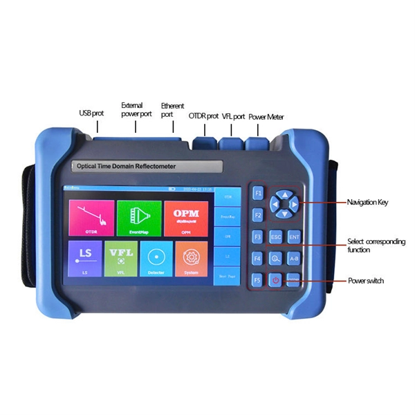
Optical power meters can measure the power of both single-mode and multimode fibers. In single-mode fiber, the rays travel down its entire length without any internal reflection at all. In multimode fiber, multiple rays enter at different angles and possibly have different wavelengths. An optical power meter (OPM) is a device used to measure the power in an optical signal. The term usually refers to a device for testing average power in fiber optic systems. The term "optical power meter" may sound generic, but in popular usage, it specifically implies a fiber optic power meter. For light power measurements outside the field of. Optical loss is measured in “dB” which is a relative measurement, while absolute optical power is measured in “dBm,” which is dB relative to 1mw optical power Loss is a negative number (like –3. It details the main components, including sensor heads and display units, and explains the two primary sensor technologies: robust thermal sensors for high powers and. The OMM-6810B is a power and wavelength meter capable of simultaneously measuring the optical power and wavelength of a laser source. A wide variety of measurement heads cover wavelength ranges from 400 to 1650 nm for power ranges of up to +40dBm or 10W. Fiber optic connections form the backbone of modern data infrastructure, yet even a small speck of dust can render a link completely.
[PDF]
Tilt sensors are devices that measure the tilt or slope of an object with respect to a reference. Fibre Bragg Grating (FBG) tilt sensors are a specific type of tilt sensor that utilizes the principle of Bragg's law in fiber optics to measure tilt angles. The tilt sensor is composed of two cylindrical floats suspended in water, connected with FBG. When the external environment causes the tilting of the sensor. Abstract—A surface-mounted tilt sensor was designed and fabricated to measure the inclination angle of engineered structures or slopes in two directions. In a FBG tilt sensor, the optical fibre is. We demonstrate a new concept for an all-fiber inclinometer based on a tapered fiber Bragg grating (tFBG) in a fiber ring laser (FRL) with the capability of measuring the tilt angle and temperature simultaneously.
[PDF]
The purpose of this study is to explore the key aspects, challenges, and future perspectives on eye-tracking studies aiming at promoting human-performance-related aviation safety. We reviewed 72 relevant.
[PDF]

In this video, we'll walk you through the process of wiring a home distribution box with a detailed connection diagram. In this article, we will delve into the details of an electrical sub panel diagram, discussing the various components, their functions, and the proper wiring techniques. Whether you are a homeowner tackling a DIY electrical project or an electrician looking to expand your knowledge, this guide will. A 30-amp sub panel functions as a secondary electrical distribution point, receiving power from the main service panel to serve a localized area. This small panel is commonly used to provide lighting and receptacle power to detached structures like a garage, a workshop, or a small shed. more Welcome to our channel! In this video. Load Calculation: Perform a load calculation to determine the total electrical load of the building. This involves calculating the power requirements of each individual device or system and adding them together to get the total load. It is important to ensure that the wiring and subpanel can handle. An electrical panel box, also known as a breaker box or a distribution board, is a crucial component of any electrical system. It serves as a central hub for distributing electricity throughout a building, ensuring that power is delivered safely and efficiently to all the required locations. ) is a cabinet or cutout box which contains on controlling and protective devices (such as circuit breakers, fuses, switches etc.
[PDF]