
UV spectroscopy is an analytical technique that measures how much ultraviolet and visible light a substance absorbs. By shining a beam of light through a sample and recording which wavelengths get absorbed, it reveals information about the sample's chemical structure, identity, and concentration. Ultraviolet–visible spectrophotometry (UV–Vis or UV-VIS) refers to absorption spectroscopy or reflectance spectroscopy in part of the ultraviolet and the full, adjacent visible regions of the electromagnetic spectrum. Being relatively inexpensive and easily implemented, this. Spectroscopy is the measurement and interpretation of electromagnetic radiation absorbed or emitted when the molecules or atoms or ions of a sample move from one energy state to another energy state. A UV-Vis spectrophotometer measures the amount of light that enters. Ultraviolet-visible (UV-vis) spectroscopy is used to obtain the absorbance spectra of a compound in solution or as a solid. Its speed, simplicity, and broad applicability make it a core method in research, quality control, and.
[PDF]
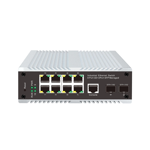
Optical modules are essential components in modern communication networks, enabling high-speed data transmission over fiber optic cables. As the demand for faster and more reliable internet and data services grows, understanding these devices becomes increasingly important. Optical modules typically have an electrical interface on the side that connects to the inside of the system and an optical interface on the side that connects to the outside. That is, metal medium communication represented by coaxial cables and network cables is gradually being replaced by optical fiber media. Composition of Optical Modules The optical module, known as Optical Transceiver in. The optical module serves as a crucial component in optical fiber communication systems, operating at the physical layer, which is the lowest layer in the OSI model. Its primary function is to achieve optoelectronic conversion by converting electrical signals into optical signals and vice versa.
[PDF]
So, how do you connect multiple sections together? The answer: use the right connection accessories for a secure, aligned and continuous cable support system. In most cases, sections of wire mesh baskets or electrical cable trays are joined using couplers, bolts, or proprietary. Connecting cable trays correctly is essential for system safety, load stability, and long-term performance. The most common cable tray connection methods include: Each method differs in installation time, cost, flexibility, and strength. The Cable Ladder & Tray Components – Assembly Guide presents a comprehensive visual walkthrough of the assembly and installation process for cable ladder and tray systems. The images meticulously detail each component involved, including ladder sections, cross-members, splices, and tray segments. Make a 90 Gusset Bend in Cable Tray with Two Pieces Easy Way To Connect Pipes 17. Joining Cable Tray - Three Sytems Explained Explanation of the three systems available for joining cable tray, delivered by Greenmill Product Trainer, Simon Makin. ” What does this mean? Cable trays support cable the way that roadway bridges. After you have drafted cable tray or conduit runs, you can break an individual segment, break an entire run, or merge multiple segments. This can be helpful for determining the number of individual segments a manufacturer needs to supply. When merging segments, you cannot cross fittings to join.
[PDF]
An optical power meter (OPM) is a device used to measure the power in an signal. The term usually refers to a device for testing average power in systems. Other general purpose light power measuring devices are usually called,, power meters (can be sensors or ), or lux meters. A typical optical power meter consists of a , measuring and display. The sens.
[PDF]

In this article, we break down the major FTTx models, compare their performance and implementation contexts, and showcase how LINK-PP's high-performance optical modules support each deployment type. Huawei's fiber to the room (FTTR) solution extends fibers to rooms and provides various gigabit Wi-Fi 6 master/slave FTTR units, all-optical components, and optical cable construction tools, enabling users to enjoy stable gigabit Wi-Fi experience in every corner of rooms at every moment. In. Fibre-to-the-room (FTTR) delivers Gigabit optical capacity directly to each room in a building, providing very high-speed, reliable internet. FTTR fibre-based technology: designed to enhance digital capabilities. FTTR addresses challenges related to restricted speeds within buildings, providing. Fiber to the Room (FTTR) is a next-generation access network designed to deliver high bandwidth, low latency, and room-level optical coverage. It is envisaged that the topology and functionalities of FTTR technologies may be. Fiber to the Room (FTTR) is a possible solution to issues with indoor connectivity. Demands for high bandwidth, high bit rates in both directions, low latency, and service reliability are constantly growing. FTTR is a very effective way to improve the quality of residential broadband service and reduce customer complaints, more so with the advent of Wi-Fi 7.
[PDF]
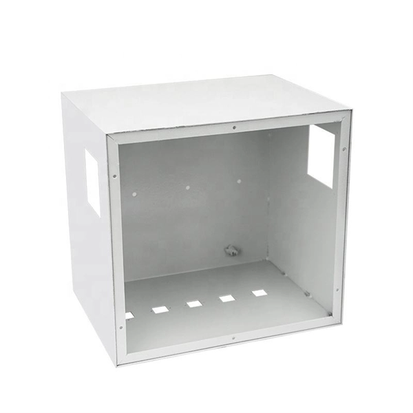
A Fiber optic cap type splice box is a protective enclosure designed to house and organize fiber optic splices. It typically features a dome or cap-style closure that provides a sealed environment for fiber joints, protecting them from external conditions. As fiber optic networks continue to expand across urban, rural, and industrial environments, the reliability of connection points becomes. The cap-type splice box is mainly designed for laying optical cables in overhead and tunnels. It does not meet the waterproof requirements of the regulations when used in direct-buried lines, but the moisture-proof effect in lines is better. According to regulations, the open type and other three. The types of optical cable splice boxes can be divided into cap-type optical cable joint boxes and horizontal optical cable joint boxes according to the shape and structure. According to. Grandway's fiber optic closure provides a high density wall mounted or pole mounted solution for next generation networks, which aims to provide and manage fiber splitters in a limited space. It is designed for FTTH (Fiber to the Home) or FTTB (Fiber to the Building) with protective housing for all. Briefly explain how fiber splice closures are critical for network protection and performance optimization. Introduce that choosing between dome (cap-style) and horizontal (in-line) closures depends on specific project requirements. Understanding Fiber Splice Closure Types 1.
[PDF]

Numerous disciplines, including photonics, telecommunications, biomedical imaging, and quantum computation, make extensive use of cube beam splitters and their techniques for manipulating light. A beam splitter or beamsplitter is an optical device that splits a beam of light into a transmitted and a reflected beam. It is a crucial part of many optical experimental and measurement systems, such as interferometers, also finding widespread application in fibre optic telecommunications. A typical cube beam splitter consists of two prisms with right-angle faces that are joined at their hypotenuses. A special dielectric coating is applied to one of these surfaces, which. 📦 For purchasing, use the RP Photonics Buyer's Guide for beam splitters. It provides an expert-curated supplier directory, buyer-focused technical background information, and structured selection criteria to support professional procurement decisions. What are Beam Splitters? A beam splitter (or. Plate beamsplitters are flat substrates with a partially reflecting coating on one surface that divides the optical beam based on power or wavelength. No epoxy or optical contacting is used in fabrication, making plate beamsplitters intrinsically suitable to high energy applications. They come in different types and have numerous applications. However, most do not know how they work.
[PDF]
A distribution box is used to receive electrical power from a main supply and distribute it to multiple branch circuits in a safe and controlled way. It helps protect circuits, organize electrical connections, and improve maintenance efficiency. Distribution. The distribution box (DB box) helps safely and efficiently distribute electrical power. Today, electrical systems are essential for homes and industries. But what exactly is a power distribution box, and why is it so essential in our daily lives? The DB panel board controls the flow of electricity. For procurement professionals, electrical contractors, and project managers, choosing the right Distribution Box (DB Box) is a critical decision that directly impacts system safety, reliability, and long-term operating costs. This ultimate guide explains what a distribution box does, its internal. A distribution box, also known as a distribution board, electrical panel, or breaker box, is an enclosure that houses electrical components responsible for distributing electricity throughout a building. They give more power and help machines work well. Tip: If you have big machines or a large building, you probably need a 3-phase box. The Main Distribution Board is the main part of your electrical system. It connects to the main power supply. It integrates power distribution, protection, and monitoring capabilities, and is responsible for distributing power to entire commercial or residential.
[PDF]
Relay protection is the discipline of designing schemes that detect faults, coordinate relays, and isolate equipment without outages. It emphasizes selectivity, coordination, fault response, and system behavior rather than individual relay devices. Relay protection is often misunderstood as a. A protective relay is an intelligent electrical device designed to detect faults in power systems and initiate corrective actions such as tripping a circuit breaker. : 4 The first protective relays were electromagnetic. This document provides recommendations, background and philosophy on relay protection that is not available in M07. The facilities to which this Document applies are generally comprised of the fol-lowing: In analyzing the relaying practices to meet the broad objectives set forth, consideration must. What is a Protective Relay? A protective relay is an intelligent device that senses abnormal electrical conditions, such as overcurrent, under-voltage, or frequency deviations. It initiates the operation of circuit breakers to isolate the affected section. This prevents damage to equipment, reduces. Protective relays and devices have been developed over 100 years ago to provide “lastline”of defense for the electrical systems. They are intended to quickly identify a fault and isolate it so the balance of the system continue to run under normal conditions. The selection and applications of.
[PDF]

They function as intermediate distribution points between: The enclosure itself does not process optical signals. Its role is structural and operational rather than active transmission control. Different box structures support different deployment layers inside FTTH and. In the complex architecture of fiber optic networks, the Optical Distribution Frame (ODF) serves as the linchpin for organizing, protecting, and distributing optical signals. Whether in data centers, telecom central offices, or enterprise network rooms, ODFs enable efficient fiber management. A Fiber Optic Distribution Box is a key device in fiber optic communication networks, used for centralized management, distribution, and protection of fiber optic connections. As an important node in fiber optic access networks (such as FTTH) and backbone networks, it ensures efficient transmission. An optical distribution frame (ODF) is a crucial component in the telecommunication industry, specifically in the area of fiber optic networks. Its role is structural and. This complete guide explores everything you need to know about ODFs — from their structure, types, and key components, to installation best practices and modern design trends. It serves as a merging point for the optical fibers, where connections are consolidated and routed, thus minimizing signal attenuation. The ODF includes.
[PDF]

They are designed to split unpolarized light at a specific Reflection/Transmission (R/T) ratio with unspecified polarization tendencies. A beam splitter or beamsplitter is an optical device that splits a beam of light into a transmitted and a reflected beam. It is a crucial part of many optical experimental and measurement systems, such as interferometers, also finding widespread application in fibre optic telecommunications. This division allows for the simultaneous analysis or utilization of the light's properties along two separate paths. The device is purely. Transmission and Reflection by. In addition to the task of dividing light, beamsplitters can be employed to recombine two separate light beams or. Explore the precision, applications, and design principles of beam splitters, essential for advancements in scientific research and technology. With WDS, a single X-ray energy – monochromatic X-rays – are counted at any given time. 19511; JEOL L-Value table2; CAMECA® SXFiveFE brochure3; Oxford Instruments Wave brochure4; Thermo ScientificTM NORANTM IbeX5). Unlike conventional beam splitters, PBSs ensure that the resulting beams are both linearly.
[PDF]

Pellicle beam splitters are made from an extremely thin membrane, often nitrocellulose, stretched over a frame. Their minimal thickness minimizes absorption and eliminates ghost images, which are secondary reflections that can degrade optical performance. Beamsplitters are fundamental components in optical engineering, serving to precisely divide a single input beam of light into two distinct output beams. This division allows for the simultaneous analysis or utilization of the light's properties along two separate paths. Their precision and versatility make them indispensable in a variety of scientific, industrial, and technological applications. These versatile tools can split both laser and regular light, depending on the application in question. Additionally, beamsplitters can be used in reverse to combine two different beams into a single one. It is a crucial part of many optical experimental and measurement systems, such as interferometers, also finding widespread application in fibre optic telecommunications. However, how they work exactly often remains overlooked. This article covers all you need to know about.
[PDF]
This article presents a novel solar photovoltaic energy harvesting system for charging the high voltage Electric Vehicle (E.V.) battery using a Partial Resonant Inverter (PRI) driven doubler rectifier circuit. The.
[PDF]


