Specialized Products offers LED and laser fiber optic light sources from AFL, EXFO, VIAVI, Photonix, Tempo Communications and other leading brands. Our selection includes multimode, single mode and quad light sources, with FC, LC, SC, ST connectors and. The state, throughput, and identification of an optical fiber can be easily checked with fiber testers by coupling highly visible laser light into the optical fiber. The red light of a laser is coupled into the core of an optical fiber in a targeted manner (an LED is usually too weak a source to be. Definition: delivery of power for electronic devices via light in an optical fiber which is converted to electricity Alternative terms: power-over-fiber, photonic power Category: fiber optics and waveguides Related: fibers fiber cables laser diodes fiber optics Page views in 12 months: 3730 DOI:. Prizmatix Silver-LED fiber-coupled LEDs provide high power continuous (CW) low noise output as well as fast pulsed operation from optical fiber. Silver-LEDs are available at deep UV, UV, Violet, Blue, Green, Yellow, Red or NIR. Fiber Coupled LED light source modules are ideal for use with high NA. This paper discusses the application of fibre optic technology and its benefits in the operation of solar power plant. Fibre optic technology enhances solar power plant operations, ensuring reliable data transmission and control.
[PDF]
GPON is an alternative to Ethernet switching in campus networking. GPON replaces the traditional three-tier Ethernet design with a two-tier optic network which eliminates access and distribution Etherne.
[PDF]
An optical power meter (OPM) is a device used to measure the power in an signal. The term usually refers to a device for testing average power in systems. Other general purpose light power measuring devices are usually called,, power meters (can be sensors or ), or lux meters. A typical optical power meter consists of a , measuring and display. The sens.
[PDF]

The mechanical dimensions of an optical power sensor can be quite relevant for applications, e.g. when a sensor needs to be temporarily inserted into some beam path, where there is little available space. There are some very flat hand-he. The mechanical dimensions of an optical power sensor can be quite relevant for applications, e.g. when a sensor needs to be temporarily inserted into some beam path, where there is little available space. There are some very flat hand-held sensors, mostly based on photodiodes, which require quite little space. Thermal power sensors are intrinsically relatively slow – particularly those for high powers, where the thermal capacity of the sensor is tentatively higher. Typical response times are of the order of 0.2 s to 2 s. Even photodiode-based power meters are normally not made very fast, since one could anyway not read a display which is updated e.g. 10. Power meters require some electrical power, which may either be provided with an external power supply or with batteries (which are normally rechargeable). Battery-powered operation is of course convenient by eliminating another cable enter the requirement of a nearby power socket, but on the other hand the need for regular recharging can also be i.
[PDF]
Commonly, a power meter on its own is used to measure absolute optical power, or used with a matched light source to measure loss. When combined with a light source, the instrument is called an Optical Loss Test Set, or OLTS, typically used to measure optical power and end-to-end optical loss.OverviewAn optical power meter (OPM) is a device used to measure the power in an signal. The term usually refers to a device for testing average power in systems. Other general purpose light power measuring. The major types are (Si), (Ge) and (InGaAs). Additionally, these may be used with attenuating elements for high optical power testing, or wavelengt. A typical OPM is linear from about 0 dBm (1 milli Watt) to about -50 dBm (10 nano Watt), although the display range may be larger. Above 0 dBm is considered "high power", and specially adapted units may measure u.
[PDF]

Optical power meters can measure the power of both single-mode and multimode fibers. In single-mode fiber, the rays travel down its entire length without any internal reflection at all. In multimode fiber, multiple rays enter at different angles and possibly have different wavelengths. An optical power meter (OPM) is a device used to measure the power in an optical signal. The term usually refers to a device for testing average power in fiber optic systems. The term "optical power meter" may sound generic, but in popular usage, it specifically implies a fiber optic power meter. For light power measurements outside the field of. Optical loss is measured in “dB” which is a relative measurement, while absolute optical power is measured in “dBm,” which is dB relative to 1mw optical power Loss is a negative number (like –3. It details the main components, including sensor heads and display units, and explains the two primary sensor technologies: robust thermal sensors for high powers and. The OMM-6810B is a power and wavelength meter capable of simultaneously measuring the optical power and wavelength of a laser source. A wide variety of measurement heads cover wavelength ranges from 400 to 1650 nm for power ranges of up to +40dBm or 10W. Fiber optic connections form the backbone of modern data infrastructure, yet even a small speck of dust can render a link completely.
[PDF]
When it comes to testing fiber optic cables, a Visual Fault Locator (VFL) is an essential tool in your toolkit. A VFL is used to detect faults, breaks, or bends in fiber optic cables by emitting a bright red light that is visible even through the fiber's jacket. Let's dive into everything you need to know about mastering VFLs. In the. Finding a break in a fiber optic cable can be challenging but is essential for maintaining a stable network. Common Indicators of a Cable Break Signal. Here Kingfisher's experienced engineers share their experience in best practices and procedures for fiber optic testing related mostly to installation and maintenance. We hope that by sharing our knowledge, we will help grow our industry. Please enjoy & pass on these notes. The following are key methods and techniques used for optical fiber cable line failure positioning: Visual Inspection: Perform a visual inspection of the. Locating faults in fiber optic cables requires specialized tools and techniques. Look for dirt, scratches, or damage on the connectors. Clean. To ensure the quality and continuity of fiber optic services, it is essential to identify and locate fiber optic cable faults as quickly and accurately as possible. In this article, you will learn about some of the common methods and tools for fiber optic testing and troubleshooting.
[PDF]
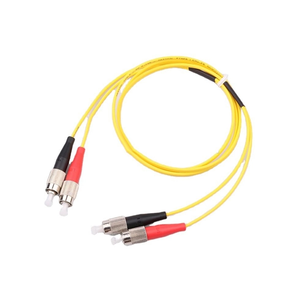
IEC fiber connector standards establish the global specifications for connector geometry, mating interfaces, optical performance classes, and mechanical testing across all fiber network environments. Optical connectors are used to connect optical devices to other optical devices or systems. However, each connection introduces a certain amount of insertion and return loss that. Connectors play an important role in Enterprise network architecture. They give you the power to add, drop, move, and change the network. is a small cylinder used to mount. The Fischer FiberOptic Series offers robust and faultless optical performances in any conditions. Combined with easy use, cleaning and maintenance. Tested for harsh and extreme environments (Norm IEC 61753-1 Cat. These standards ensure that passive fiber-optic components remain interoperable, stable, and. designed for diverse fiber optic applications. But what exactly sets a fibe optic connector apart in terms of its merits? The primary purpose of a fiber optic connector is to terminate the ends of fiber optic cables, ensuring they can be int rconnected reliably with minimal optical loss. After. Fiber optic technology is used in ever-increasing applications due to its inherent advantages (lower weight, EMI/RFI immunity, higher bandwidths and distances) over copper. There are many.
[PDF]

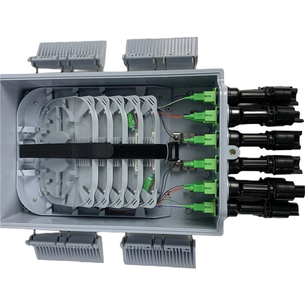
The fibers within a butterfly cable are housed in a tight buffer, reducing their exposure to tension and ensuring that any strain applied to the outer jacket does not translate directly to the optical fibers. The invention provides a flexible physical flame-retardant low-friction compression-resistant butterfly-shaped optical cable and a production method thereof, and relates to the field of optical cables. The optical fiber core is located in the center of the cable body, two reinforcing cores are placed on both sides, and the outer layer is enveloped and sheathed to form a cable. FTTH (Fiber to the. Fiber optic technology has revolutionized internet connectivity, and the Butterfly Fiber Optic Cable GDX702 stands at the forefront of this innovation. As fiber optic cable manufacturers continue to refine their products, understanding the technical intricacies becomes crucial for network planners. FTTH butterfly optic cables are specially engineered to facilitate high-speed internet connections directly to residential homes. Their name stems from the distinctive "butterfly" shape, which is a result of their layered construction. Its innovative design positions the communication unit at the core, flanked by two parallel non-metallic strength members (FRP) for enhanced compression resistance and.
[PDF]
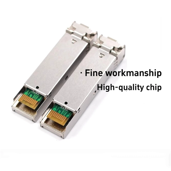
Light sources are devices that generate the optical signals transmitted through fiber optic cables. In fiber communication, the most commonly used light sources are LEDs (Light Emitting Diodes) and laser diodes. LEDs are used in short-distance, low-speed systems due to their broader spectral width. Optical fiber primarily uses infrared light, not visible light, due to lower signal attenuation. Common wavelengths are 1310nm and 1550nm, where silica glass fiber has minimal loss (as low as 0. Lasers or LEDs generate the light, which carries data through total internal reflection within. Most systems use a "transceiver" which includes both transmission and receiver in a single module. The transmitter takes an electrical input and converts it to an optical output from a laser diode or LED. It often uses glass or plastic cables, which address the problems of traditional copper cables' poor speed and limited distance bandwidth carrying. VCSEL (Vertical Cavity Surface Emitting Laser)- VCSELs (pronounced 'vixel') emerged in the 80's as a new kind of semi-conductor laser and were soon recognized for their potential in fiber optics. When Gigabit Ethernet products were developed LEDs could not modulate (turn on and off) at required.
[PDF]

Learn how to splice fiber optic cable using fusion splicing with this complete step-by-step guide. Includes tools, best practices, loss standards (ITU-T G. 652), cost analysis, and FAQs for network engineers and installers. Splicing fiber optic cable is an extremely important phase for making dependable, high-speed communication infrastructures. Regardless of the type of fiber network you're deploying, be it for telecom, enterprise data centers, or smart city infrastructure, fusion splicing provides the benefits of. This is where fiber optic cable splicing—the process of creating a permanent, high-performance join between two fiber ends—becomes critical. For network managers and technicians, a poor splice can lead to significant signal degradation, network downtime, and costly troubleshooting. At Turn-Key. Think of a fiber optic cable splice as the seamless stitching that keeps data flowing through the delicate threads of a network—like a master tailor joining fabric with precision. What is Fiber Optic Splicing and Why is it Needed? – #1. Discover how to efficiently use sleeves and the heat. The answer lies in splicing, both fusion and mechanical. In this comprehensive guide, we will delve into when.
[PDF]
The communication system of fiber optics is well understood by studying the parts and sections of it. The major elements of an optical fiber communication system are shown in the following figure. The ba.
[PDF]
Fibre-optic Link Around the Globe (FLAG) is a 28000km (17,000miles) fibre optic mostly- submarine communications cable that connects the United Kingdom, Japan, India, and many places in between. The cable is operated by Global Cloud Xchange, a subsidiary of RCOM. These cables stretch thousands of kilometres beneath the sea, carrying the digital world across continents. New Delhi: Internet is an inseparable part of life in this modern world. Social media. These undersea cables carry almost all international data, connecting continents and countries. They're like the invisible highways of our digital world. Today, tech giants like Google, Facebook, Amazon, and Microsoft own or lease more than half of the undersea bandwidth. The world depends on digital links and the control of these cables decides how information moves between. Private telecom and technology companies own and operate nearly all submarine internet cables, which carry 99% of global internet traffic. These companies invest heavily in laying and maintaining the vast network of fiber-optic cables that connect continents and enable international data flow. The system runs from the.
[PDF]