
A lighting control module operates as the central controller for a lighting system. It receives input from switches, apps, or sensors and regulates electrical flow to connected lights. Depending on the setup, it adjusts brightness, color temperature, or full lighting scenes. It acts as a bridge between your physical lighting fixtures and the smart systems that manage them. Instead of relying solely on traditional wall switches, you can control your lights via remotes, mobile or web apps. A lighting control module is an essential component in a lighting control system that manages how lights are powered, dimmed, or switched on and off. Think of it as the “brain” that receives commands—either from a manual switch, a sensor, or a building automation system—and translates them into. A lighting control module is a smart device that manages lighting circuits, adjusting brightness, automating schedules, and responding to sensors. It enhances comfort, efficiency, and ambience in homes and commercial spaces. Explore the multifaceted benefits and applications of lighting control modules, from home automation to industrial. These modules are designed to communicate with various sensors, switches, and control panels, making lighting adaptable to different environments and user preferences. It enables precise management of lighting systems, allowing for adjustments in brightness, color, timing, and even integration with other smart devices. This innovation.
[PDF]

These data switches are responsible for routing and data switching at the core layer of the network. The data routed and switched by the core switch is carried forward to the bottom layers of the network such as the distribution and access layer. Engineered to aggregate massive volumes of data from distribution switches, it provides ultra-low latency and maximum throughput to ensure uninterrupted routing and packet. The significance of the core switch in building and sustaining a resilient network infrastructure is paramount. This determines network efficacy, dependability, and the speed at which. There are different types of enterprise switches that perform various roles in these layer-based or hierarchical ethernet networks. The hierarchy Ethernet network. A core switch in networking serves as the high-capacity backbone, italic centralizing data flow and ensuring efficient communication between different network segments. Simply put, it's the kingpin that keeps your network humming. You may also want to know: Can a Nintendo Switch Play DS Games? ·. A core switch is the backbone of a large-scale network, designed to handle massive volumes of traffic with ultra-low latency and maximum reliability.
[PDF]

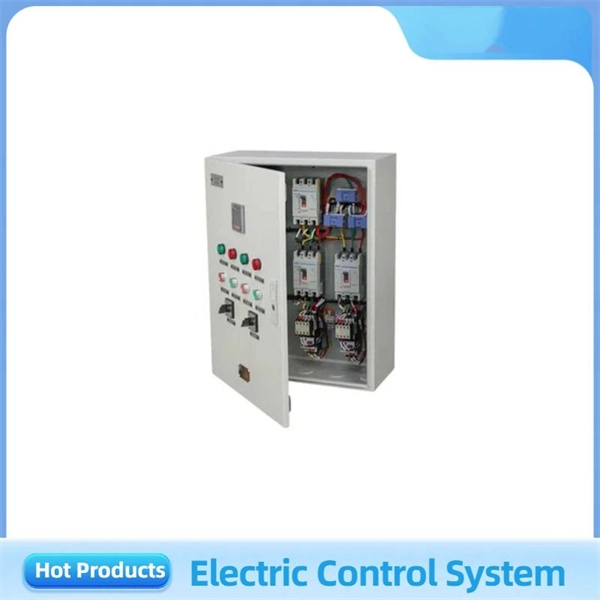
More specifically, these systems keep tabs on voltage, current, and temperature limits and control the disconnect relay. This allows them to disconnect themselves from the external application in case of malfunction. From a drop of rain to the shining sea, an energy storage system is like the earth's bodies of water (hear us out). In a battery energy storage system (BESS), the energy in the battery cells is like raindrops that combine to form a brook. Made of the combined energy from cells, these brooks combine. Battery energy storage systems (BESSs) investment is expected to grow to $103 billion by 2030. ) Battery systems aren't just designed to serve as local power backups, such as the systems used to power critical facilities (including hospitals and data centers) when the normal. When a 300 MWh battery energy storage system (BESS) in Arizona tripped offline during July's heatwave, operators discovered voltage fluctuations had overwhelmed its protection relays. Could your facility withstand such stress? As global BESS installations surge—projected to reach 1. Protection is necessary when energy and voltages combine from the modules, as well as from the battery racks. Fuses are an efficient. The electrical integration design of a Battery Energy Storage System (BESS) is based on the application scenario and includes various aspects such as DC, high/low voltage distribution, control power distribution, grounding, lightning protection, and safety standards.
[PDF]

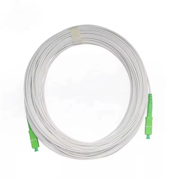
The optical fiber cold joint is used when two pigtails are docked. The main part inside it is a precise V-shaped groove. It is used to connect optical fiber or optical fiber butt pigtail, which is equivalent to making a joint (fiber butt pigtail refers to the butt joint of the fiber core of the optical fiber and the pigtail instead of the pigtail head mentioned in the former), and is used for this kind of cold. When installing a fiber optic network, connectors are required to connect both ends of the fiber optic cable. Common splicing methods include optical fiber cold splicing and optical cable hot fusion splicing. Advantages and disadvantages of fiber optic cold splicing Fiber cold splicing refers to. Mechanical splicing involves physically aligning and holding two fiber ends together using mechanical means. This method is typically used for permanent connections, but it allows for disassembly without damaging the fiber ends. Mechanical splices are often preferred for their simplicity and. Optical fiber transmission offers numerous advantages, including a wide frequency bandwidth, high communication capacity, low signal loss, immunity to electromagnetic interference, compact cable size, and the availability of abundant raw materials. As a result, it has become a preferred medium for. Executive Summary: A fiber optic pigtail is one of the most commonly specified yet least understood components in structured cabling.
[PDF]

For most setups, cables with 12, 24, or 48 cores are common choices, ensuring compatibility with modern equipment and ease of management. Fiber cores are the heart of fiber optic cables, transmitting light signals that carry data. Made from either high-quality glass or plastic, the core plays a critical role in determining the cable's performance. The total number of cores for a 1pc fiber patch cable is calculated as the number of. In fiber optic cables, data is transmitted as pulses of light that travel along a thin strand of glass or plastic fiber. The light is typically. The number of optical cores in an optical fiber is the total number of equipment interfaces multiplied by 2, plus 10% to 20% of the spare quantity, and if the communication mode of the equipment has serial communication and equipment multiplexing, you can reduce the number of cores. The following ZR Cable introduces some methods to determine the number of fiber cores. First of all, clearly know the number of wiring points in this layer, calculate the number of switches, and whether the connections. A fiber-optic cable, also known as an optical-fiber cable, is an assembly similar to an electrical cable but containing one or more optical fibers that are used to carry light. ” However, when light enters the core it needs to remain within it, and one layer that ensures that is called.
[PDF]

The document discusses optical detectors used in fiber optic communications systems. It describes the functioning of PIN photodetectors and avalanche photodetectors (APDs). Their performance. An optital detector is a device that converts light signals into electrical signals, which can then be amplified and processed. Such detectors are one of the most important components of an optical fiber communcation system and dictate the performance of a fiber optic communication link. PIN Photodiode A PIN photodiode is a widely. Detectors perform the opposite function of light emitters. The most common detector is the semiconductor photodiode, which produces current in response to. It explains how these devices use optical fibers to measure quantities like temperature, mechanical strain, pressure, and vibrations by detecting changes in light propagating through the fiber. A central focus is on sensors based on fiber Bragg gratings, where the Bragg wavelength is sensitive to. Optical Power Meters: These devices measure the power of optical signals in fiber optic cables. This information helps in maintaining signal integrity and quality across the.
[PDF]

Optical couplers can split or join signals in fibers. You can connect many users to one port with 1:n or 2:n splitters. These devices work both ways, which helps strong network communication. They help send. This small device connects or joins optical fibers together. It helps networks grow and change when needed. Learn about the two main types of fiber optic couplers: fused and planar. Fused. How to Choose the Right Fiber Coupler (FTTH, Data Center & More) Are you in the process of designing a Fiber to the Home (FTTH) network, but wondering how to split one fiber for multiple users? Or maybe you are operating a data center, and you would like to use a single signal to provide to. Fiber optic couplers are optical devices that connect three or more fiber ends, dividing one input between two or more outputs, or combining two or more inputs into one output. The device allows the transmission of light waves through multiple paths. Fiber optic couplers can either be passive or. A fiber optic coupler is a passive optical component that splits, combines, taps, or redistributes light between optical fibers. In real-world networks, couplers let one signal reach many users, allow several signals to share one fiber path, or sample a small amount of light for monitoring. 5/125 µm fiber, with low insertion loss and a broad operating wavelength range from 800 to 1600 nm. The 1x2 and 2x2.
[PDF]
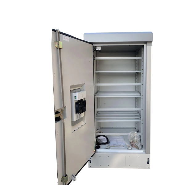
FTTH Networks: Wall-mount panels are used in apartment basements to distribute signals to individual units. Data Centers: High-density 4U panels are used for Top-of-Rack (ToR) switching. Broadcast & Media: Used for high-bandwidth 4K/8K video signal routing. This 2026 expert guide explains the functions, placement, structure, and application scenarios of ODFs and fiber patch panels-and includes a deep engineering FAQ that resolves real-world deployment challenges. Where Do ODF and Fiber Patch Panels Fit in a Modern Fiber Network? To understand the. Depending on different network construction scales and application environments, fiber optic cabinets and patch panels are typically used in various combinations. Choosing the right structural combination can significantly improve network construction efficiency. First is the standard. A Fiber Optic Patch Panel, also known as an Optical Distribution Frame (ODF) or fiber termination enclosure, is a centralized hardware unit designed to manage, protect, and organize fiber optic cable connections.
[PDF]

President Ibrahim Mohamed Solih highlighted on Friday the importance of connecting the country to the international fibre cable system, stating that it is a crucial step in establishing the Maldives as a hub for technology and innovation. The President's remarks at the inauguration of the Ocean. Today, we're announcing Dhivaru, a new Trans-Indian Ocean subsea cable system that will connect the Maldives, Christmas Island and Oman. This investment will build on the Australia Connect initiative, furthering the reach, reliability, and resilience of digital connectivity across the Indian Ocean. A new domestic Maldivan subsea cable from Dhiraagu and Ooredoo has landed on the island of Hulhumalé in the North Malé Atoll. Dubbed the Domestic Submarine Cable of Maldives (DSCoM), the telecommunications cable has five segments and will connect eight islands in the Maldives including Hulhumale'. Huawei Marine today announced that it has partnered with Ooredoo Maldives to deploy a Nation-wide Fiber Optic Submarine Cable, which will support the country's broadband policy and give the Maldives the most advanced ICT infrastructure in the SAARC region. The nationwide submarine cable utilizes.
[PDF]
No, a 10G SFP (Small Form-factor Pluggable) module is designed to operate at 10 Gigabits per second (Gbps) and is not compatible with a 1 Gigabit per second (Gb) port. Therefore, a 10G SFP module will not work. When SFP optical module is inserted into the SFP port of Gigabit switch with fiber optic patch cable or copper cable, it can realize different distance transmission. For example, the maximum transmission distance is 160 km when using SFP1G-ZXC-55 optical module and LC duplex fiber patch cable, and. 10 Gigabit Ethernet (10GE, 10GbE, or 10 GigE) is a group of computer networking technologies for transmitting Ethernet frames at a rate of 10 gigabits per second. It was first defined by the IEEE 802. For example, when using the AE-SFP-ZX160 optical module and LC duplex fiber optic patch cords, the maximum transmission. Can 1G SFP optics work with 10Gb SFP+ ports on a 10Gb switch, or vice versa? This comprehensive guide reveals the intricacies of SFP and SFP+ compatibility and provides useful solutions for network switch users. Can 1G SFP Optics Run at 10G SFP+ Port? Can 10G SFP+ Optics Run at 1G SFP Port? Can. Small form-factor pluggable or SFP Modules can be described as compact and hot-pluggable hardware that connects various networking devices such as servers, routers, and switches. Networking standards, including Ethernet, Fiber Channel, and SONET, are also used with the SFP modules, broadening their.
[PDF]
Several types of tray are used in different applications. A solid-bottom tray provides the maximum protection to cables, but requires cutting the tray or using fittings to enter or exit cables. A deep, solid enclosure for cables is called a cable channel or cable trough. A ventilated tray has openings in the bottom of the tray, allowing some air circulation around the cables, water drainage, and allowing some dust to fall through the tray. Small cables may exit the tray throug.
[PDF]

One rack unit equals 1. 45 mm), defined by the EIA-310. Measure your deepest server and add 3–6 inches for cabling and airflow. While rack height is standardized in rack units (U), external dimensions vary by manufacturer. A rack space calculator is a specialized tool designed to help data center professionals, IT administrators, and network engineers determine the optimal placement and space requirements for equipment in server racks. This calculator helps you plan rack layouts by calculating the total rack units. Server rack height is measured in rack units (U). Use the. When planning LAN infrastructure, selecting the correct data rack size is essential for proper equipment fit, ventilation, cable management, and future expansion. A practical formula often used for estimating the required rack size is: Rack size = 1. Common sizes: 42U, 48U, and compact options like 22U–27U. Standard width is 19 inches (EIA-310 compliant), while outer widths vary (e. Rack depth matters for. The three primary dimensions to consider are rack height (measured in rack units or U), rack width (most commonly the industry-standard 19-inch format), and rack depth (typically ranging from 24 inches to 48 inches). Each of these factors influences equipment fit, airflow management, cable routing.
[PDF]
While a college degree isn't strictly required, completing a fiber optic training program and obtaining industry certifications are essential. Some employers may prefer candidates with an associate's degree in electronics or a related field. The Fiber Optic Association, Inc. The charter of the FOA was to promote professionalism in fiber optics through education, certification, and. When planning a fiber optic installation, understanding the unique considerations of new construction fiber optic projects is essential. These projects often involve designing a cable layout that aligns with the specific needs of the site while anticipating future scalability. Clearly defining the. d suppliers of electrical construction services. NEIS® are intended to be referenced in contrac documents for electrical construction ation or liability to users of this publication. The FBA OpTIC Path™ course consists of 144 hours of instructor-led and hands-on practices to equip future fiber technicians with the skills and knowledge required to install, splice, test and maintain. Starting with site surveys and permissions, to installing fiber optic cable and emphasizing the process as a key stage in mastering fiber optic installation, to the careful handling of cables and high-stakes splicing, each stage is critical. From the initial site survey to the final fiber to the home (FTTH) connection, every stage requires careful planning, coordination, and.
[PDF]
