In this guide, you will find a chronological description of the fusion splicing process, the principal technical standards, and answers to the real-life questions network engineers and procurement teams may have. 📦 For purchasing, use the RP Photonics Buyer's Guide for fusion splicers. It provides an expert-curated supplier directory, buyer-focused technical background information, and structured selection criteria to support professional procurement decisions. This article explains the principle of fusion. Fusion splicers play a crucial role in the field of optical fibre communications by enabling the permanent bonding of two strands of glass fibre to create a continuous pathway for light to travel through. This process is achieved through precise alignment and fusion of the fibre ends using an. Fusion splicing is the process of fusing or welding two fibers together usually by an electric arc. Fusion splicing is the most widely used method of splicing as it provides for the lowest loss and least reflectance, as well as providing the strongest and most reliable joint between two fibers. Each splicer is equipped with a cleaver and stripper, conveniently includes in a single case. The goal is to align the microscopic glass cores (typically.
[PDF]

Main cost drivers include on-site labor, specialized fusion splicing, testing, and any necessary restoration of network performance. This guide provides practical cost ranges in USD with clear low–average–high estimates to help budgeting and planning. Fiber optic splicing costs vary widely depending on project size, location, fiber type, and site conditions. For most commercial projects, expect to pay $50–$150 per fusion splice point — but that number can swing in either direction based on the factors below. The "per splice" rate is the most. There are two primary methods of splicing fiber optic cables: fusion splicing and mechanical splicing. Each method has distinct characteristics and costs associated with it. Fusion Splicing: This method involves aligning two fiber ends and using an electric arc to melt them together, creating a. Adtell Integration is capable of supporting your fusion splicing requirements whether they require Singlemode, Multimode, or Ribbon Splicing. Fusion Splicing Services: Contractor/Customer Fusion Splicing & Installation Services: Adtell integration offers nationwide fusion splicing services. Specifically fiber used for internet. -W2 employee for a decent size telecommunication contractor, all.
[PDF]

The Optical Time Domain Reflectometer (OTDR) is useful for testing the integrity of fiber optic cables. It can verify splice loss, measure length and find faults. The OTDR is also commonly used to create a "picture" of fiber optic cable when it is newly installed. The Contractor tasked to perform testing or splicing on any fiber optic cable will follow these testing standards to fulfill their contractual obligations. The Contractor must utilize the correct equipment and testing techniques to gain acceptance, or the work cannot be approved. Later, comparisons can be made. For every fiber optic cable plant, you will need to test for continuity, end-to-end loss and then troubleshoot the problems. If it's a long outside plant cable with intermediate splices, you will probably want to verify the individual splices with an OTDR also, since that's the only way to make. ic system. Fiber optic testing of a newly installed system not only verifies that the system meets its design requirements, but also creates a performance baseline for all future testing and troubleshooting of t at system. What is Fiber Optic Splicing and Why is it Needed? – #1. Use and Maintain Your. This guide reveals the secrets to fusion splicing with little fluff—just proven, straightforward techniques refined from years of work in the field. The guide provides the complete workflow, covering safety precautions, tool selection, fiber preparation, fusion operation, quality control, and.
[PDF]

Because fiber optic cables don't come in one continuous length, sections must be joined together through splicing. This process fuses two glass strands so light signals can travel through them without interruption. Below is a detailed look at each step of fiber optic network construction, including key terms and methods used across the industry. Engineers and. We are experts in the installation and use of fiber optic cable to residences, apartment buildings, businesses and cell sites. We complete complex construction projects consisting of aerial and underground deployments in varied, often difficult, working environments. Our services include everything. The Fiber Optic Association, Inc. (FOA) was founded in 1995 to help develop the workforce to build the fiber optic networks to support a rapid expansion in communications and the Internet. Delivers state-of-the-art fiber optics solutions by developing high-tech equipment and subcontractor expertise. Utilizes state-of-the-art technologies to splice a wide variety of different. This recommended practices document is a comprehensive manual for optical fiber construction and testing. Sections are included for project management; cable handling, testing and equipment; overhead cable placement; underground cable placement; underground enclosures; bonding and grounding; cable. 4. FO-VC2 JOINT USE - VERICAL MIDSPAN CLEARANCES 48. FO-GB GROUNDING AND BONDING 49.
[PDF]
Splice Diagrams or Matrices capture an electric or optical network inside a location – documenting cables, ported equipment, and connections. Splices are fiber-to-fiber, port-to-fiber and port-to-port. Fiber optic cable splicing involves joining two fiber optic cables together. Another method of connecting optical fibers is termination or connectorization, which consists of processing the end of a fiber optic bundle so that it can be connected to other fibers or devices through fiber optic. In this guide, we cover the basics of fiber optic splicing, how to perform splicing using two different methods, and finally some best practices to perform good fiber splicing. Ensure Your Splicing Tools are Clean – #2. Use and Maintain Your. What to show on a network diagram? Fiber optic network diagrams represent the architecture and connectivity of fiber optic systems, and their design philosophy integrates technical, functional, and conceptual aspects. The diagrams abstract complex details of fiber optic systems to make them. This Geoschematics drawing remains easy to read despite containing more than 2000 fibers and 500 splices. All students and instructors must wear safety glasses in this lab. It is copyrighted by the FOA and may not be distributed without FOA permission. This VHO covers similar material to the videos on YouTube. The lab manual has several.
[PDF]

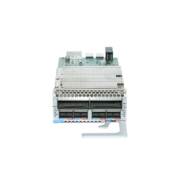
Mechanical Optical Switches: Switching times typically range from 1-10ms, suitable for long-distance transmission scenarios where latency is not critical (such as backbone network protection switching). Solid-State Optical Switches: Based on thermooptic or electrooptic effects, response. We lead the industry in optical switch technology, delivering the lowest insertion loss (0. 2 dB), fastest switching speed (10 ns), broadest wavelength range (300–2400 nm), widest fiber compatibility, highest optical power handling (50 W), and space-qualified reliability. Backed by over 25 years of. Use this optical switches buying guide to compare major types, define selection criteria, and find suppliers: Professional purchasing of high-value photonics products is a substantial responsibility, where a structured decision-making process is essential. RP Photonics offers a lot of help: Get. This document is a troubleshooting and selection guide for common optical switch failures, compiled based on over 500 field cases. These switches are built on proven, reliable optomechanical technology that has seen more than 30 years of successful operation. Each. The POLATIS ® Series 7000 384x384 all-optical circuit switch is designed to meet the most demanding applications with exceptionally low optical loss, compact size, and fast switching speeds. With support for Software-Defined Networks (SDNs) via embedded NETCONF and RESTCONF control interfaces, the.
[PDF]

In this paper, various operational factors affecting 100G transmission over G. D fiber-cables are discussed to make the right fiber selection for the long-haul network. Selecting appropriate G. 652 fibre was originally optimized for use in the 1310 nm wavelength region but can also be used in the 1550 nm region. This is the latest revision of a Recommendation that was first created in 1984 and deals with some relatively minor modifications. a number of concatenated cable. G. 92% of. Fiber optic cables are the ultimate technology used in data transfer using light waves. They are classified based on wavelength band, core/cladding size, application, and compliance with international standards such as IEC, ITU-T, and TIE/EIA. In the next sections, the real artwork is putting on. This guide explains the most important ITU-T G. 655—to help you make an informed decision for your project, whether it's a long-haul backbone or a final FTTH drop. In the world of fiber optics, not all glass is created equal. The core of every cable—the optical. Because GPON and XGS-PON are deployed in diverse environments, fiber-containing components such as PLC splitters must be evaluated not only by their standard parameters but also by their sensitivity to bending loss, which is critical for maintaining stable optical transmission. The ITU-T defines.
[PDF]

This report lists the top Fusion Splicer companies based on the 2023 & 2024 market share reports. Mordor Intelligence expert advisors conducted extensive research and identified these brands to be the leaders in the Fusion Splicer industry. Fujikura Europe Ltd offers fusion splicers, which are essential for efficiently joining optical fibers. As the official support center for Fitel splicers, OFS. AFL - Fiber optic cable, transmission and substation accessories, outside plant equipment, connectors, fusion splicers, test and inspection equipment. Discover how these fusion-spliced, field-installable connectors simplify installation and improve performance. Are you looking for a professional and reliable fiber optic products manufacturer for your business? Are you still worried about how to find and select a best partner from so many fiber optic products manufacturers? Don't be afraid, Gcabling will help you. In this post, Gcabling, as a professional. Fiber splicing is the process of joining optical fibers to create continuous, low-loss optical pathways used in manufacturing, research, and high-performance fiber systems. In advanced applications, fiber splicing is not a single operation. They are headquartered in locations across the globe, including the United States, China, Brazil, and India, with founding years ranging from 1964 to 2019.
[PDF]

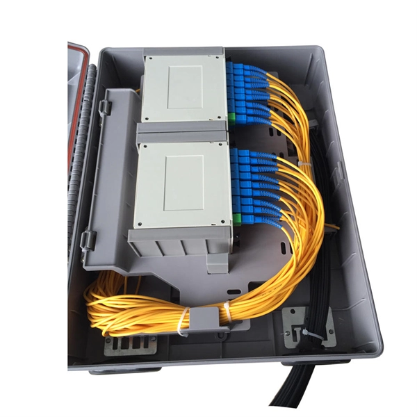
Learn how to install fiber splice trays inside an enclosure step by step. Quick, easy, and essential for fiber pigtail management! https://bit. Unlike fiber connectors, which can be plugged and unplugged, splicing creates a fixed connection that is typically more stable and has lower insertion. This document describes the installation of optical fiber with both single fiber and/or ribbon fiber splices into Optical Splice Enclosure (OSE) metal splice trays (Figure 1). Make sure you read and understand this instruction as well as instructions provided with related assemblies before. By following these detailed steps, the installation of your Fiber Splice Closure will be secure, organized, and maintained, ensuring high performance and longevity of your fiber optic network. Installing a fiber optic splice closure efficiently and effectively requires attention to detail and. How to install the splitter distribution box is the important information we need to know. This article includes the following: 1. Install the fixture 2. Box installation and fixed splitter distribution box 4. Install. Page 5 B (# 7 & 8) enter splice tray # 2. Route the fibers entering the splice tray up to splice point as shown. NOTE : Protection tube from side A enters splice tray from the far end as shown After splicing, close the splice tray and lock the front cover properly with the main and side lock.
[PDF]

The two primary industry-accepted methods for fiber optic cable splicing are fusion splicing and mechanical splicing. The choice between them depends on performance requirements, budget constraints, and the specific application environment. To begin, the standard definition of splicing in optical fiber is joining two fiber optic cables together. Splicing is most commonly used in the field but has application in cable assembly houses. Infield. In this guide, we cover the basics of fiber optic splicing, how to perform splicing using two different methods, and finally some best practices to perform good fiber splicing. What is Fiber Optic Splicing and Why is it Needed? – #1. In this guide, we'll explore what splicing of fiber entails, why it's important, and dive into the key methods and tools. So in essence, fiber optic splicing is a process used to join two separate fiber optic cables together. Through splicing, fiber optic technicians can extend the length of the fiber to make it long enough for use in a required cable run. As. Splicing fiber optic cable is an extremely important phase for making dependable, high-speed communication infrastructures. Termination is the other, more frequent way of linking fibers. Fiber splicing is the preferred way when cable lines are too long for a single length of fiber or when combining two different types of cable.
[PDF]
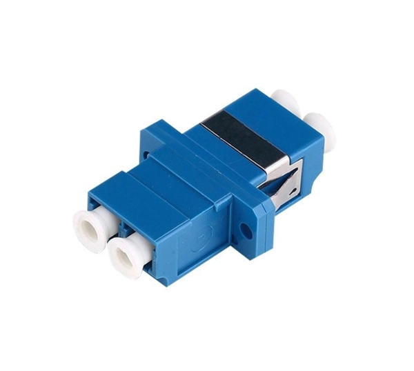
Fiber optic splicing is the process of joining two fiber optic cables together so that light signals can pass with minimal loss or reflection. Splicing is typically required during cable installation, maintenance, or network expansion. Another method of connecting optical fibers is termination or connectorization, which consists of processing the end of a fiber optic bundle so that it can be connected to other fibers or devices through fiber optic. When deploying fiber optic cabling, one of the most critical decisions is how to terminate the fiber—either by splicing or using connectors. Both techniques have their advantages and are suited for different applications, but understanding which method to use can greatly impact the network's. Fiber optic splicing, crucial for maintaining seamless connectivity in modern communication networks, primarily uses two methods: fusion splicing and mechanical splicing. Fusion splicing provides a low-loss, highly reliable connection by melting and fusing fiber ends, making it ideal for long-haul. As fiber optic connections become increasingly mainstream, the need to connect fiber optic cables to one another — or splicing — is also on the rise. Get the wrong connector type, the wrong polish, or skip proper fusion splicing technique—and you're looking at elevated signal loss, increased back reflection, and a.
[PDF]
In this comprehensive guide, we delve into the intricacies of fiber optic splicing—encompassing methodologies, instruments, and best practices—while highlighting Dekam Fiber's state-of-the-art offerings that facilitate durable networks. It's the process of joining two fiber optic cables using techniques such as fusion splicing and mechanical splicing, crucial for maintaining uninterrupted communication networks. In this guide, we'll explore what splicing of fiber entails, why it's important, and dive into the key methods and tools. Fiber termination refers to the process of preparing the end of a fiber optic cable to connect to another fiber, a device, or a network. Proper termination is essential for ensuring optimal performance, reducing signal loss, and maintaining the durability of the connection. Unlike using connectors, which are designed for frequent connection and disconnection at patch panels, splicing creates a permanent, stable joint with minimal light loss. What is Fiber Optic Splicing and Why is it Needed? – #1. Use and Maintain Your. Splicing fiber optic cables involves precisely joining two fiber ends to create a continuous optical path. This article explores how to splice fiber, focusing on achieving minimal signal loss and ensuring reliable data transmission through the proper fusion splicing techniques and mechanical.
[PDF]