
In this video, we'll walk you through the process of wiring a home distribution box with a detailed connection diagram. Whether you're an electrician or a DIY enthusiast, this guide will help you understand the basics of home electrical distribution. more Welcome to our channel! In this video. A distribution box is the heart of any electrical system. It takes the incoming power and safely distributes it to different circuits throughout your building. However, the key to. Material preparation: Prepare the required circuit breakers, wires, wiring ties and other materials, and ensure that they meet the design drawings and installation requirements. Location determination: Determine the installation position of the circuit breaker according to the position of the. In modern electrical systems, cable distribution boxes (also known as electrical distribution boxes or distribution boxes) play a crucial role as the key hub for managing, distributing, and protecting circuits. Whether it is residential buildings, commercial facilities or industrial sites, the. Hey, in this article we are going to see the Single Phase Distribution Box Wiring Diagram and Connection Procedure. A distribution board or distribution box is where the main power supply is distributed to multiple loads.
[PDF]
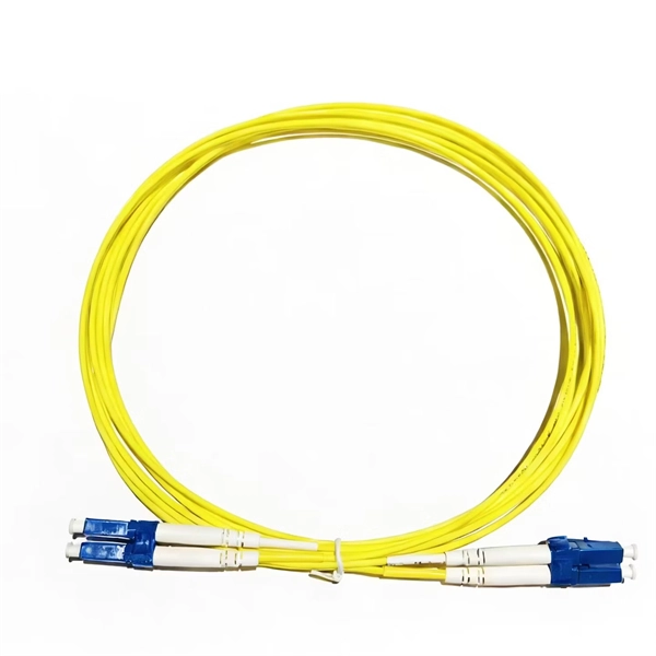
When laying loops of fiber on a surface during a pull, use “ figure-8 ” loops to prevent twisting the cable. Bending of a fiber optic cable can damage the cable if the radius of the bend is too small. However there are some general rules that should be. If the cable remains outside for more than 24h during installation protective material should be used to prevent cable damage. The maximum installation and storage temperatures specified for each cable in the data sheet must be respected. The specified values apply to the cable temperature and not. Tension on the cable and pulling ropes can cause twisting. Use a swivel pulling eye to connect the pull rope to the cable to prevent pulling tension causing twisting forces on the cable. Roll the cable off the spool instead of spinning it off the spool end to prevent putting a twist in the cable. The device prevents the cable from twisting as it travels over pulling blocks. Left uncontrolled, the optical cable's delicate glass fibers could be permanently damaged during installation. We do so appreciate your efforts. It happens during installation, when excessive pulling force, tight bends. Fiber optic cable bend radius is a critical mechanical parameter that determines how sharply a cable can be bent without risking microbending, macrobending, signal loss, or long-term structural fatigue. Proper bend radius control ensures the integrity of optical performance and protects the glass.
[PDF]
In this video, we'll walk you through the process of wiring a home distribution box with a detailed connection diagram. Whether you're an electrician or a DIY enthusiast, this guide will help you understand the basics of home electrical distribution. more Welcome to our channel! In this video. This guide provides step-by-step instructions for connecting a distribution box and highlights key factors to consider during installation. What Is a Distribution Box? A distribution box, also known as an electrical distribution board, is a critical component in electrical systems. It takes the incoming power and safely distributes it to different circuits throughout your building. However, the key to. A junction box provides a necessary protective enclosure for all electrical wire splices and connections, which must never be left exposed within a wall or ceiling. It serves as a central hub for distributing electricity throughout a building, ensuring that power is delivered safely and efficiently to all the required locations.
[PDF]
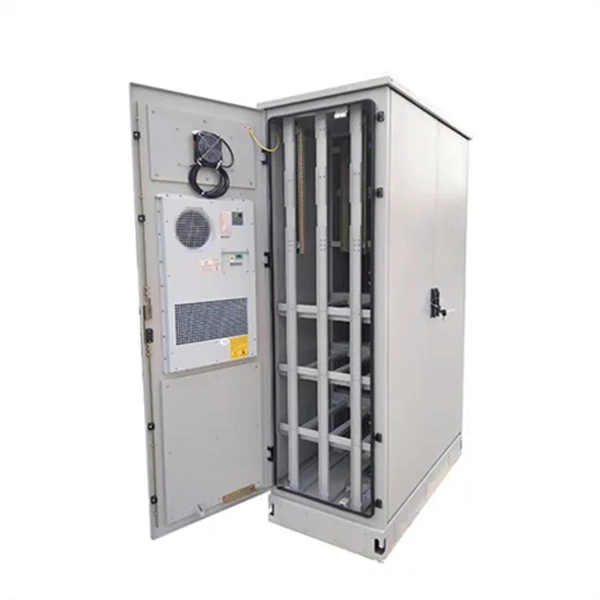
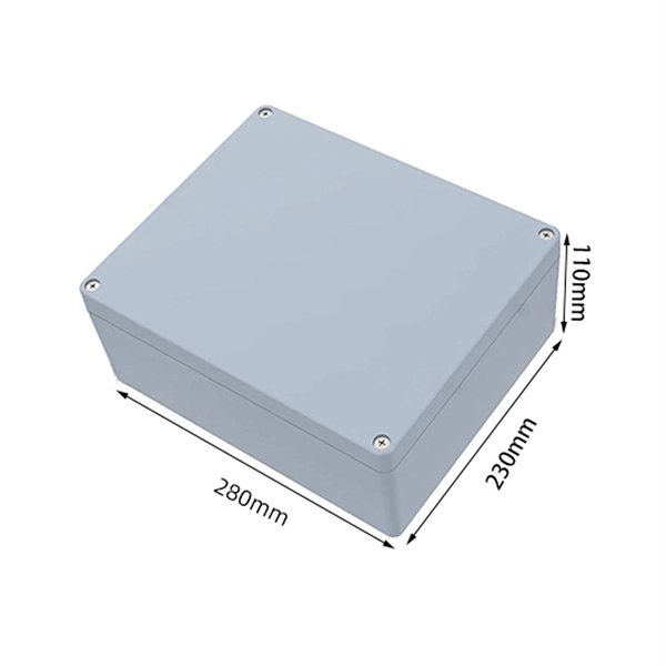
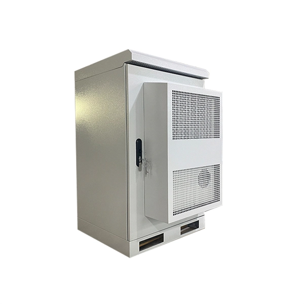
This video shows real on-site footage of electrical installation, demonstrating safe and standardized wiring methods used by professionals. Let's break it down into two main parts: the outer shell and the electrical parts inside. The enclosure protects the electrical components from water, dust, and damage. When choosing one, check the IP or NEMA rating. A. The ideal location to install electrical distribution boxes should keep a distance from water, flammable and explosive substances and corrosive substances. If they need to be placed outdoors, especially in high humidity, you must ensure their waterproofness. Below is a quick checklist of everything you will need for a safe and efficient installation: Connecting a distribution box involves several steps to ensure proper electrical flow. Follow this guide. Box installation: Make sure that Distribution box has been correctly installed and fixed. Material preparation: Prepare the required circuit breakers, wires, wiring ties and other materials, and ensure that they meet the design drawings and installation requirements. Location determination:. Understanding the wiring diagram of an electrical panel box is essential for electricians and homeowners alike, as it allows them to troubleshoot any electrical issues, carry out repairs, or make additions to the system. The electrical panel box wiring diagram provides a visual representation of.
[PDF]
Connect the input and output wires to the corresponding terminals of the distribution box. Then press the wire onto the terminal with a wire stripper, or tighten the wire with screws. This step is very crucial and can not bear any faults!. In this video, we'll walk you through the process of wiring a home distribution box with a detailed connection diagram. more Welcome to our channel! In this video. This guide provides step-by-step instructions for connecting a distribution box and highlights key factors to consider during installation. What Is a Distribution Box? A distribution box, also known as an electrical distribution board, is a critical component in electrical systems. It serves as a central hub for distributing electricity throughout a building, ensuring that power is delivered safely and efficiently to all the required locations. It is usually equipped with circuit breakers, fuses, terminal connectors, and other components.
[PDF]

The easiest way is to use the $3 "spec-grade" receptacles which come in a box instead of loose in a bin. If it's just black and white wires with a cloth or plastic covering and no ground wire you'd need a retroit grounding wire to have grounded outlets. A clearer picture of the cable entering will help. Can you post photos that show clearly where the cables enter the box at, please? @Traveler No!. The process of wiring a small breaker box, often called a subpanel, is a common task when adding power to a detached structure like a shed, garage, or a major home addition. These smaller distribution centers are designed to take power from a larger main service panel and distribute it locally to. How do I wire a mini circuit breaker distribution box that doesn't have bus bars? I have a circuit going to my shed from my house and I want to have two separate breakers inside the shed (one for outlets, one for other stuff) so I bought this from amazon (Amazon. com: 2 Way Distribution Box Circuit. In this video, we'll walk you through the process of wiring a home distribution box with a detailed connection diagram. more Welcome to our channel! In this video. Connecting a distribution box involves several steps to ensure proper electrical flow. But first, the rules: Turn off the power when working with electricity. Make sure the power's off using a non-contact voltage tester or multimeter. One final tip: Get into the habit of making connections in this.
[PDF]
Fiber optic cable suspension clamp installation manual made by Jera line. Developed to provide a quick access to attach the fiber optic cable to the pole, using the suspension clamp HC-8-15, stainless steel band, buckles and strapping tool MBT-004. more. This guide will explain the entire set of activities involved in installing Fiber optic cable contractors -from the early planning stage right through testing-for facility managers, IT teams, and low-voltage contractors to build high-performance networks safely and efficiently. The processes. You simply can't handle and install fiber optic cable using the same methods that are used for copper. The relative fragility of fiber when compared to copper cable requires special care, special practices, and attention to detail during handling and installation. (FOA) was founded in 1995 to help develop the workforce to build the fiber optic networks to support a rapid expansion in communications and the Internet. The charter of the FOA was to promote professionalism in fiber optics through education, certification, and. The FIBERLIGN Suspension uses a combination of structural reinforcing rods (SRR), outer rods, housing halves, and resilient inserts to reduce compression, clamping, and bending stresses on OPGW and the optical fibers within it. SRR and outer rods cannot be reused. Different environments demand different fiber optic cable installation methods: aerial cables strung on poles.
[PDF]

In this video, we'll walk you through the process of wiring a home distribution box with a detailed connection diagram. This guide provides step-by-step instructions for connecting a distribution box and highlights key factors to consider during installation. What Is a Distribution Box? A distribution box, also known as an electrical distribution board, is a critical component in electrical systems. Whether you're an electrician or a DIY enthusiast, this guide will help you understand the basics of home electrical distribution. It serves as a central hub for distributing electricity throughout a building, ensuring that power is delivered safely and efficiently to all the required locations. It is usually equipped with circuit breakers, fuses, terminal connectors, and other components. It is mainly used to isolate fault circuits, prevent overload, and ensure the safe operation of. The steps to install a small distribution box include selecting a suitable location, installing the base, placing the distribution box, connecting the wires, and checking for acceptance. Warm reminder: Do not disassemble or modify without experience and professionals. Select location Before.
[PDF]

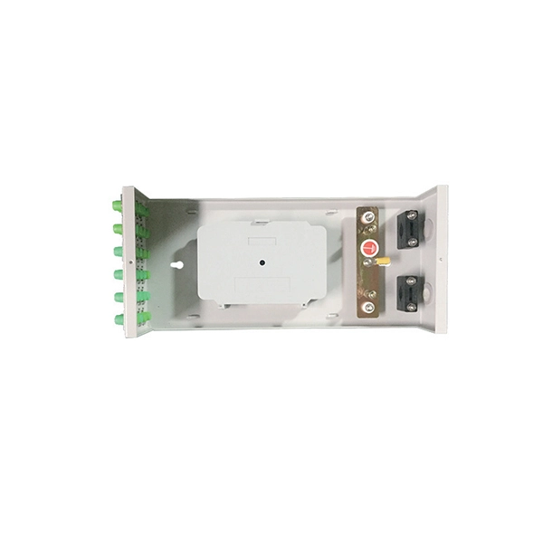
In this guide, we'll walk you through the entire process of preparing fiber optic cable for splicing and termination to fiber connectors. We'll explore the necessary tools, safety precautions, and step-by-step procedures for cable connectors, mechanical and fusion. At the heart of any robust fiber optic network lies a crucial process: Preparing a fiber cable for termination of a connector or splice. Two types of splices are used in fiber optic cabling one is Mechanical the other is Fusion. Whether you're installing a new network, expanding an existing one, or. Splicing fiber optic cable is an extremely important phase for making dependable, high-speed communication infrastructures. Regardless of the type of fiber network you're deploying, be it for telecom, enterprise data centers, or smart city infrastructure, fusion splicing provides the benefits of. Think of a fiber optic cable splice as the seamless stitching that keeps data flowing through the delicate threads of a network—like a master tailor joining fabric with precision. This article explains when. We terminate fiber optic cable two ways - with connectors that can mate two fibers to create a temporary joint and/or connect the fiber to a piece of network gear or with splices which create a permanent joint between the two fibers. These terminations must be of the right style, installed in a. So in essence, fiber optic splicing is a process used to join two separate fiber optic cables together.
[PDF]
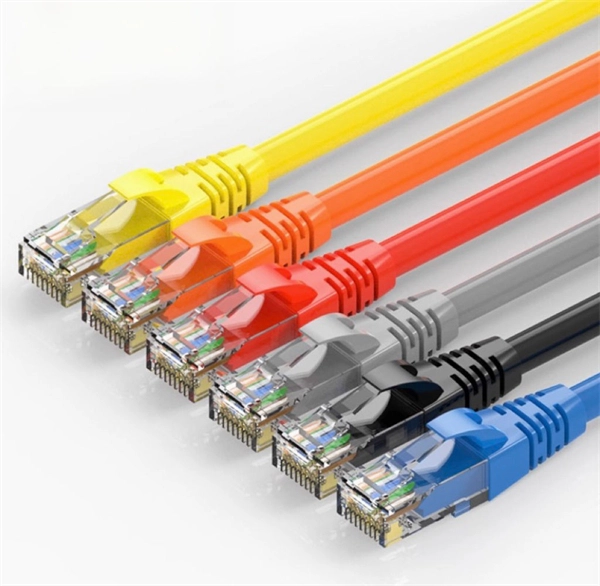
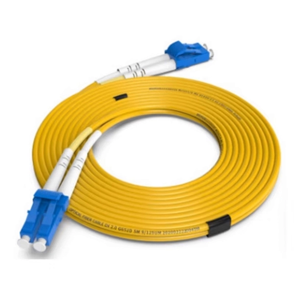
These installation instructions provide overview and specification information for small form-factor pluggable (SFP/ SFP+/SFP28) modules, as well as instructions for installing and removing the modules. SFP (Small Form-factor Pluggable) transceivers are essential components in modern fiber optic networks, enabling network devices such as switches, routers, and servers to transmit and receive data over optical fiber. By converting electrical signals into optical signals—and vice versa—SFP. Gigabit single-mode fiber optic module Common parameters of optical modules 1. Center wavelength 1) 850nm (MM, multi-mode, low cost, but short transmission distance, usually only 500M); 2) 1310nm (SM, single mode, large loss during transmission, small dispersion, generally used for transmission. As a leading provider of fiber optic solutions, Weunion offers a wide range of SFP-compatible products, including optical transceivers, DAC/AOC cables, LC patch cords, and MPO/MTP assemblies. While they may appear to be simple plug-in transceivers, SFP modules are precision-engineered devices that directly influence network. o In optical modules, "core" refers to the light-transmitting channel in the fiber. A 1-core module uses a single fiber core for data transmission, while a 2-core module uses two cores. o Think of a highway. A 1-core fiber is like a single-lane road—only one car (or data signal) can travel at a.
[PDF]
CT-S3T-2 tower section weight does not exceed 26 kg. Transmission tower weight per meter varies dramatically by voltage level: 35kV towers average 100-180 kg/m, 66kV systems run 150-250 kg/m, 110kV towers range 200-450 kg/m, 220kV structures reach 350-600 kg/m, and 500kV ultra-high voltage towers require 500-800 kg/m. This weight increases. Due to the complicated nature of tower infrastructure, it can prove invaluable to have an engineer approved recommendation for solutions that will accommodate your particular project. We offer a Tower Recommendation Proposal Consultation Service, providing a detailed report that you can use for the. 18m Telecom Tower Ma /www. inf. ASMTower automatically performs load calculation on telecom structures, wind load, ice load and dead load according to the following design standards: ASMTower performs wind and ice load calculations according to the chosen code and distributes the resulting loads, along with the weight of the. Get Latest Price from the seller Khan Enterprises - Offering Selp Sport Wi-Fi Tower, Size: 18 Mtr Rtt at ₹ 3500/meter in Bengaluru, Karnataka. Get WiFi Tower at lowest price | ID: 20500615430. Now, let's take a look at the pricing options: 1. Non-upgradeable: • 12 meters: R49,990. 00 ex VAT ex works PLUS R49,000. 00 ex VAT for site visit, civils, and installation.
[PDF]
- **Third-level Distribution Box**: That is, the switch box, which is at the end of the power distribution system and directly provides power for electrical equipment. It is closely connected to the electrical equipment. A distribution box is installed under the main distribution box, and a switch box is installed under the distribution box. "Two level protection" mainly refers to the use of leakage protection measures. In. Note: Distributions by generation are defined by birth year as follows: Silent and Earlier=born before 1946, Baby Boomer=born 1946-1964, Gen X=born 1965-1980, and Millennial=born 1981 or later. Last Update: March 27, 2026 The Federal Reserve Board of Governors in Washington DC. Residential utility pole diagrams are essential for understanding the infrastructure that provides electricity, telephone, and internet services to homes. The following is a detailed introduction about it: - **First-level Distribution. Electric power distribution is the final stage in the delivery of electricity. Electricity is carried from the transmission system to individual consumers. Distribution substations connect to the transmission system and lower the transmission voltage to medium voltage ranging between 2 kV and 33 kV.
[PDF]
Beamsplitters are commonly employed in lasers to create different beam paths, achieving this effect by dividing the laser beam into multiple segments and then recombining them. This allows the direction and intensity of the beam to be adjusted with outstanding precision and. Beamsplitters are fundamental components in optical engineering, serving to precisely divide a single input beam of light into two distinct output beams. This division allows for the simultaneous analysis or utilization of the light's properties along two separate paths. It is a crucial part of many optical experimental and measurement systems, such as interferometers, also finding widespread application in fibre optic telecommunications. In its. This article explains how to create a beam splitter cube in Sequential Mode. One of the biggest challenges for modeling such a system is that multiple ray paths cannot be simultaneously traced in Sequential Mode. These versatile tools can split both laser and regular light, depending on the application in question. Beamsplitters are often classified according to their construction: cube or plate. Beam splitter divides a beam of light into two or more separate beams. Beam splitters can be made from different materials and are often coated with thin layers of metal or dielectric materials.
[PDF]
