In this comprehensive guide, we will walk you through the step-by-step process of wiring outdoor outlets safely and effectively. 💡 Quick Answer: An outdoor electrical junction box is a weatherproof enclosure where electrical wires connect or split, required by code to protect connections from moisture, provide safe access for maintenance, and prevent electrical hazards in exterior applications. Properly wiring outdoor outlets enhances safety, functionality, and convenience. However, because outdoor electrical work involves. Installing an outdoor electrical panel box requires careful planning and execution. This guide covers everything you need to know for a safe installation. Understanding local electrical codes is paramount; these regulations ensure safety and compliance. Using the right tools, such as a voltage. Outdoor wiring faces harsher conditions than indoor installations as it is exposed to moisture, sunlight, and mechanical damage. Outdoor Receptacles (NEC 210. 9. An outdoor breaker box with integrated outlets is a specialized electrical assembly that serves as a weather-rated subpanel or load center. Designed for exterior use, it often features pre-wired receptacles directly on the enclosure. It takes the incoming power and safely distributes it to different circuits throughout your building. However, the key to.
[PDF]

This paper presents a set of newly developed modeling, simulation and testing tools aimed at better understanding the design concept and related applications for protective relaying and substation automation solutions for the smart grid. presentation of protection and control relaying. The report will identify methodology behind these practices, present issues raised by the integration of microprocessor relays and the internal logic and external communication configurations, ying. At Keentel Engineering, we specialize in modeling, simulating, and deploying advanced protective relays to ensure the robustness of medium-voltage (MV) and high-voltage (HV) networks. Our engineering services help utilities, OEMs, and renewable developers simulate real-world contingencies and. This Modern Power System Protective Relaying training course has been designed to provide a clear and perfect understanding of power system protection schemes and devices, including protection relays, fuses, circuit breakers, and other protective devices. In modern power systems, nowadays. To ensure that protective relays, circuit breakers, and other protection devices correctly and selectively isolate faults, minimizing damage to equipment and interruptions to customers while maintaining system stability. One-line diagrams and detailed network data (lines, transformers, buses).
[PDF]
As a critical component in high-speed networks, fiber optic patch cords require micron-level precision. This guide unveils the complete production workflow compliant with **IEC 61754** and **Telcordia GR-326-CORE** standards, featuring proprietary quality control. If you've ever troubleshot a fiber optic network only to find that a microscopic dust particle caused the entire system failure, you understand why IPC-8497-1 exists. This standard represents the industry's collective wisdom on how to properly clean and assess contamination in optical assemblies. For harsh environments or other data center and IT networking applications where there is a greater risk of damage to your fiber optic network, armored fiber optic cables deliver the protection you require. Built with a steel-armored layer that provides extra crush and rodent resistance, these. Welcome to be our agent! Fiber optic patch cords, also known as fiber jumpers, are essential components in high-speed data transmission networks. Their performance directly impacts signal quality, insertion loss (IL), and return loss (RL). At ZION Communication, we design and manufacture a full range of fiber patch cords for: This guide will help you quickly understand the main types of. Ensuring the performance and reliability of fiber optic patch cords is fundamental to optical network integrity. 6-Step Manufacturing.
[PDF]

More specifically, these systems keep tabs on voltage, current, and temperature limits and control the disconnect relay. This allows them to disconnect themselves from the external application in case of malfunction. From a drop of rain to the shining sea, an energy storage system is like the earth's bodies of water (hear us out). In a battery energy storage system (BESS), the energy in the battery cells is like raindrops that combine to form a brook. Made of the combined energy from cells, these brooks combine. Battery energy storage systems (BESSs) investment is expected to grow to $103 billion by 2030. ) Battery systems aren't just designed to serve as local power backups, such as the systems used to power critical facilities (including hospitals and data centers) when the normal. When a 300 MWh battery energy storage system (BESS) in Arizona tripped offline during July's heatwave, operators discovered voltage fluctuations had overwhelmed its protection relays. Could your facility withstand such stress? As global BESS installations surge—projected to reach 1. Protection is necessary when energy and voltages combine from the modules, as well as from the battery racks. Fuses are an efficient. The electrical integration design of a Battery Energy Storage System (BESS) is based on the application scenario and includes various aspects such as DC, high/low voltage distribution, control power distribution, grounding, lightning protection, and safety standards.
[PDF]

Common methods of protecting busbars include overcurrent-based interlocking schemes, overcurrent-based differential protection, high-impedance differential protection, and percentage differential protection. Interlocking and overcurrent differential protection can be implemented with any suitable. DEFINITIONS. IV EXECUTIVE. Busbar Differential Protection Definition: Busbar differential protection is a scheme that quickly isolates faults by comparing currents entering and leaving the busbar using Kirchoff's current law. Current Differential Protection: This protection method connects CT secondaries in parallel and. Busbars play an important role in power transmission and distribution. They are employed as a central distribution point for all feeders. The problem is that the busbars. Busbars have typically been left without dedicated protection, from the following reasons: It is a fact that the risk of a short circuit happening on modern metal clad equipment is insignificant, but it cannot be completely dismissed. Nevertheless, the damage resulting from one short circuit may be. 25 kV insulation is required. These heat-shrinkable tubes for straight and bent busbars are extremely flexible, allowing them to be easily positioned on busbars and quickly instal ed using a gas torch or oven. They have a high expan-sion ratio, so each size of tubing fits a range of busbar sizes.
[PDF]
The various protective functions available on a given relay are denoted by standard. For example, a relay including function 51 would be a timed overcurrent protective relay. An overcurrent relay is a type of protective relay which operates when the load current exceeds a pickup value. It is of two types: instantaneous over current (IOC) relay and definite time overcurrent (DTOC) relay.
[PDF]

A relay protection tester is a core device used to verify the performance of relay protection devices. Its working principle can be summarized as “signal excitation – behavior detection. ”. It is divided into two parts: the main loop and the auxiliary loop. ” The tester has a built-in high-precision programmable power supply, capable of simulating various operating. When the transformer wiring type is Y/Y (Y0), the test wiring is very simple: when testing phase A, the tester IA is connected to the phase A of the high voltage side, and the tester IB is connected to the phase a of the low voltage side. After the neutral line of the high and low voltage sides is. Relay protection aids in detecting and preventing faults in electrical systems such as overcurrents or short circuits. As a core part of electric system reliability and safety, protective relays aid in preserving equipment and maintaining stability by isolating affected zones automatically via. THEY SHOULD BE GIVEN FIRST LINE MAINTENANCE ATTENTION. COMPREHENSIVE INSPECTION, MAINTENANCE AND TESTING PROGRAM. ” relay may only need to operate for 0. 15 seconds in its 30+ year life. But failure to operate as intended can result in extensive damage, extended power outages, and loss of life. NETA. Megger's smart relay testing solutions and expert support help you validate protection performance, improve system reliability, and ensure continuity of power across your network.
[PDF]

The six-phase sequence current protection tester is an advanced device used to verify complex protection devices. Its core principle lies in the simultaneous output of six independent current and voltage signals to simulate various normal and fault conditions in a power system. It not only supports. In the complex world of power system protection, the Six Phase Relay Protection Test Set has emerged as an indispensable tool for engineers and technicians. These advanced devices play a critical role in verifying the reliability and accuracy of protective relays, ensuring the safe operation of. The CMC 356 is the universal solution for testing all generations and types of protection relays. Its powerful six current sources (three-phase mode: up to 64 A / 860 VA per channel) with a great dynamic range, make the unit capable of testing even high-burden electromechanical relays with very. JBC-806tester can simultaneously outputstandard six-phase current and six-phase voltage with 30A/phase current and 125V/phase voltage. With its six-phase output, this tester provides comprehensive testing capabilities, making it an essential instrument for ensuring the. nation in general. Not influenced by load, they contribute to protection speed and sensitivity. However, sequence components are present for a range of conditions, not only faults: open pole, load and line unba ance, breaker pole scatter, and current transformer ratio errors and saturation, to name.
[PDF]

In this video, I'll show you how to build a simple and effective short circuit protection circuit using a relay. This DIY project is perfect for anyone looking to protect their electronics from accidental shorts. Last Updated on February 15, 2026 by Swagatam 117 Comments In this post I will try to explain the making of a simple 220 V, 120 V AC mains short circuit breaker using an SCR and a triac combination, (researched and designed by me). The circuit is an electronic version of the normal main circuit. One possible solution to the problem of overcurrent is to use a variable bench power supply with a current limit function. These power supplies allow You to set a current limit, preventing a high current flow when a mistake occurs. This circuit will. Why Publish? How to Make Short Circuit Protection Circuit: Hii friend, Today I am going to make a circuit for Short Circuit protection. This circuit we will make using 12V Relay. How this circuit will Work - when short circuit will occur on the load side then the circuit will be automatically cut o. In this tutorial, we will see how to make a short circuit protection using Relay. Many times accidentally terminals of batteries and other power supplies get short-circuited. Due to this, they get hot and start degrading. In the case of lithium-ion or lithium-polymer batteries, they may catch fire.
[PDF]
Get Latest Price from the seller Ganesh Electrical - Offering Sifang Relay at Rs 145000 in Gadag, Karnataka. Get Protective Relays at lowest price | ID: 2853527303391. CSC-211 Multifunction Protection IED is selective, reliable and high speed protection IED with rich functions to cover following applications: 1) Protection, bay control unit, MU (Merging Unit), and SCU (Smart control Unit) in one IED; 2) Work as feeder or capacitor bank protection IED; 3) Work as. Copyright © 2020,SIFANG All Right Reserved. Protection relays detect abnormal operating conditions in an industrial system and may trigger an alert or isolate the offending device from the system. The devices can be used for line protection in networks that are grounded, low-resistance grounded, ungrounded, or of a compensated neutral point structure. It is able to supervise. Sifang Relay Install at existing Switch Gear.
[PDF]
Distance relays, also known as impedance relay, differ in principle from other forms of protection in that their performance is not governed by the magnitude of the current or voltage in the protected circuit but rather on the ratio of these two quantities.OverviewIn, a protective relay is a device designed to trip a when a is detected. The first protective relays were electromagnetic devices, relying on coils operating on moving par. Electromechanical protective relays operate by either, or. Unlike switching type electromechanical with fixed and usually ill-defined operating voltage thresholds. Electromechanical relays can be classified into several different types as follows: "Armature"-type relays have a pivoted lever supported on a hinge or knife-edge pivot, which carries a moving contact. These relays may.
[PDF]

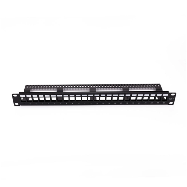
Review cutout sizes and modules. See specs, datasheets, order online. Vertical Distribution Managers are available in 8” and 12” widths. The VDM offers quick and easy cable routing for high density cable installation. Optional dual front doors offer easy access to cables and provide an elegant look for your data center. Cable fingers and spools support cables as they. Cable entry frames and kits for enclosures, panels simplify routing and strain relief. 91 inches in height and intended for use with 42U relay racks. It is used to organize cables on a relay rack which helps maintain proper airflow. Forward facing and equipped with a hinged front cover, it makes cable access quick and easy. The manager can also be. The M Series has been specifically designed to meet the demanding & varied requirements for protection relay applications in power utility sub-station environments. The standard 4U high 19-inch rack mounting modular configuration simplifies panel design & installation. Mounting points & overall. Weight capacity: 2,000lb. K04. Rackmount Mart - Rackmount Chassis and Rackmount LCD Source. Provide rackmount chassis, rackmount, rackmount lcd, rackmount monitor, kvm switch, disk array, single board computer, industrial computer, mobile rack, server rack, power supply, server case, raid tower, pc case, accessory, cabinet server.
[PDF]
The K factor (or zero-sequence compensation factor) adjusts the measured impedance for the phase-to-ground fault loop by accounting for the contribution of zero-sequence currents. This compensation is critical because zero-sequence current introduces an offset in the fault impedance. The protection and control devices in electrical equipment can be referred to by numbers, with appropriate suffix letters when necessary, according to the functions they perform. These numbers are based on a system that is adopted by a standard for automatic switchgear by Institute of Electrical. The following Terms are used in protective relaying: 1. Fault Clearing Time 5. Drop Out or Reset value 8. Sealing Relay or holding Relay 10. Time-graded protection is implemented using overcurrent relays with either definite time characteristic or inverse time characteristic. The operating time of definite time relays does not depend on the magnitude of the fault cur-rent, while the operating time of inverse time relays is shorter the. Displaying title 47, up to date as of 5/06/2026. Title 47 was last amended 4/30/2026. There have been changes in the last two weeks to Part 90. Without proper. Also principles of various protective relays and schemes including special protection schemes like differential, restricted, directional and distance relays are explained with sketches. The norms of protection of generators, transformers, lines and capacitor banks are also given. The procedures of.
[PDF]


