
Complete pv combiner box wiring diagram guide covering string connections, grounding methods, bonding requirements, and NEC-compliant installation procedures for solar systems. Most wiring diagrams supplied with commercial combiner boxes are simple, easy-to-understand. A clear wiring diagram helps installers understand the flow of current from each string to the main DC bus, making the system safer and easier to maintain. For systems with three or more DC strings, using a solar combiner box is recommended according to international PV safety standards such as IEC. This wiring diagram will guide you in understanding how to properly wire a PV combiner box. One of the key elements of a PV combiner box is the array of fuses or circuit breakers. These safety devices protect the solar panels from overcurrent and short circuits. Understanding proper wiring topology, conductor sizing methodology, and grounding. ing connections,fusing,and grounding. Following the diagram will help ensure the safety,efficiency,and long-term perform nce of your solar panel installat el off the outer shea h of the cable. Check if t is level. Check vertica deviation. Bandage exposed wire. Mea ure. This piece will address the components required for a DC PV combiner box, how to read its wiring diagram and provide a step-by-step tutorial on how to wire it safely and efficiently.
[PDF]
Welcome to our channel! In this video, we'll walk you through the process of wiring a home distribution box with a detailed connection diagram. What is Distribution Board? Distribution board. These smaller breaker panels, also known as sub-distribution boards, are commonly used to provide power to secondary circuits within a building. Understanding the components and wiring configuration of an electrical sub panel is essential for safe and efficient electrical installations. In this. Primary distribution systems consist of feeders that deliver power from distribution substations to distribution transformers. A feeder usually begins with a feeder breaker at the distribution substation. Many feeders leave substation in a concrete ducts and are routed to a nearby pole. This breaker must be compatible with both your main system and the additional connections. Typically, a 60-amp or 100-amp breaker will be suitable, depending on the load requirements. It includes isolator, RCCB (Residual current circuit breaker) or RCD (Residual-current device) devices, protective fuses or MCB's (Miniature Circuit Breaker).
[PDF]

This AutoCAD DWG file includes a complete Single Line Diagram (SLD) of a Distribution Board, showing circuit breakers, wiring connections, and load distribution for lighting, power, and mechanical systems. An electrical panel box, also known as a breaker box or a distribution board, is a crucial component of any electrical system. It serves as a central hub for distributing electricity throughout a building, ensuring that power is delivered safely and efficiently to all the required locations. Whether you're an electrician or a DIY enthusiast, this guide will help you understand the basics of home electrical distribution. What is Distribution Board? Distribution board. Welcome to our channel @Electricalgenius In this video, we'll take you through a detailed step-by-step guide on wiring a home distribution DB (Distribution Board) box. A distribution board (also known as a service panel or breaker box) is a centralized collection of circuit breakers, fuses, and/or relays used to control and protect the wiring in a home. The diagram. To understand how a breaker box works, it is helpful to have a wiring diagram that shows the connections between the various components. At the heart of a breaker box is the main breaker, which controls the flow of electricity from the utility into the building. This breaker is connected to a.
[PDF]

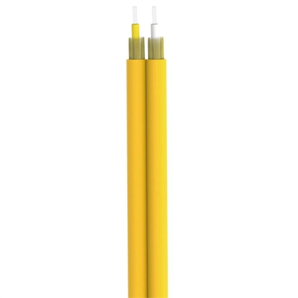
In this guide, you will find a chronological description of the fusion splicing process, the principal technical standards, and answers to the real-life questions network engineers and procurement teams may have. In this guide, we cover the basics of fiber optic splicing, how to perform splicing using two different methods, and finally some best practices to perform good fiber splicing. What is Fiber Optic Splicing and Why is it Needed? – #1. Use and Maintain Your. This Geoschematics drawing remains easy to read despite containing more than 2000 fibers and 500 splices. Splice Diagrams or Matrices capture an electric or optical network inside a location – documenting cables, ported equipment, and connections. Splices are fiber-to-fiber, port-to-fiber and. This guide will walk you through the complete process of fiber optic splicing—covering each step in detail so you can deliver a clean, professional splice every time. Before jumping into the physical steps, it's important to understand the two primary methods of fiber splicing: fusion splicing and. Page 1 The FOSC 450 fiber optic splice closures use compressed-gel cable seals to environmentally seal fiber cable splice points. FOSC 450-ab-c-dd-e-fgh The maximum single splice capacity of the FOSC 450 B6 closure is a = Closure size 144 with 24 splices stored on six trays. Therefore, we will also touch on cost factors, risk management, and best practices in.
[PDF]
Practice good wiring: secure grounding, neat cable management, proper insulation, and correct wire gauge and breaker size. Include protection devices like breakers, fuses, and surge protectors—each circuit should have its own protection. Comply with standards: Follow NEC, IEC . An electrical panel box, also known as a breaker box or a distribution board, is a crucial component of any electrical system. It serves as a central hub for distributing electricity throughout a building, ensuring that power is delivered safely and efficiently to all the required locations. In this video, we'll walk you through the process of wiring a home distribution box with a detailed connection diagram. Whether you're an electrician or a DIY enthusiast, this guide will help you understand the basics of home electrical distribution. more Welcome to our channel! In this video. Choose the right box based on environment (indoor/outdoor), load capacity, and durability. Check for proper IP/NEMA ratings and material quality. Ensure safe placement: install in dry, accessible areas with good ventilation and at appropriate height (typically ~1. It involves connecting wires and components properly, to ensure safety and efficiency. Good wiring is vital to prevent electrical hazards and keep appliances, lights, and other electrical devices functioning well. It receives power from the main electrical supply and divides it into separate circuits, each.
[PDF]
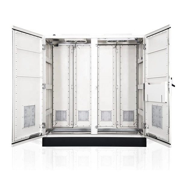
The proper installation of a distribution box involves placing it at the right height to ensure safety and convenience. 7 meters) high makes it easily accessible without the need to bend or stretch excessively. This height also safeguards the box from potential. An outdoor electrical distribution box serves as the critical junction point where incoming power lines are split into multiple branch circuits for outdoor installations, parking lots, building exteriors, and industrial facilities. Check for proper IP/NEMA ratings and material quality. Ensure safe placement: install in dry, accessible areas with good ventilation and at appropriate height (typically ~1. Practice good wiring: secure. Household distribution boxes can be installed on the ground or on the wall. Ground-mounted foundations should be 50 to 100 mm above ground level. When flused installed in the wall, the bottom is 1. 2m away from the ground. One outdoor receptacle is required at the front and rear of the house and in the perimeter of each deck, porch, patio, or balcony that is connected to the home. To run electrical. Clearance: Electrical panels must be installed in a readily accessible area with a minimum clearance of 30 inches (762 mm) wide, 3 ft (36 inches or 914 mm) deep, and 6. 5 feet (≈ 2 meter) high in front of the panel. The panelboard's door (hinged cover) shall be able to be opened to a full 90°.
[PDF]

The most common materials used for cable tray production are galvanized steel, stainless steel, and aluminum. Galvanized steel offers a cost-effective solution with good corrosion resistance. Stainless steel provides superior corrosion protection, making it suitable for harsh. A typical cable tray production line encompasses several key stages. These coils are then uncoiled and flattened through a leveling machine. Next, the material is slit to the required width for the tray. Selecting the right raw material for cable trays is vital to maintaining structural integrity, longevity, and cost efficiency. This article dives into the nuances of cable trays raw material, analyzing market trends, cost control strategies, and material innovations. The choice of raw material for. The production process of cable tray manufacturers usually includes the following main steps: Raw material preparation: The main raw materials for cable trays are usually stainless steel, galvanized steel plates, aluminum alloys, etc. It's strong, durable, and can withstand a lot of wear and tear.
[PDF]
The primary distribution box refers to the main distribution box, typically located in the distribution room. These boxes feature bottom entry and exit cables, front-opening doors, and main busbars connected with copper strips for optimal contact. The terms primary, secondary, and tertiary distribution boxes are relative. Let's make an example for clarity: A newly constructed residential area introduces a 10kV power line to a substation. From the transformer's low-voltage side (0. Main Distribution Board (MDB) 2. Unitized Panel. A distribution board (also known as panelboard, circuit breaker panel, breaker panel, circuit breaker, electric panel, fuse box or DB box) is a component of an electricity supply system that divides an electrical power feed into subsidiary circuits while providing a protective fuse or circuit. Two common types are the main panel and the distribution panel. They work together to keep your lights, appliances, and machines running safely. In this article, we'll explain what each panel does, how they are different, and when you need them. Whether it's for a home or a large building, knowing. At its core, a distribution box, also known as a distribution board, panelboard, or fuse box, is a protective enclosure that houses all the electrical components that control and protect the circuits in a building. It receives a single, high-amperage power feed and divides it into multiple.
[PDF]

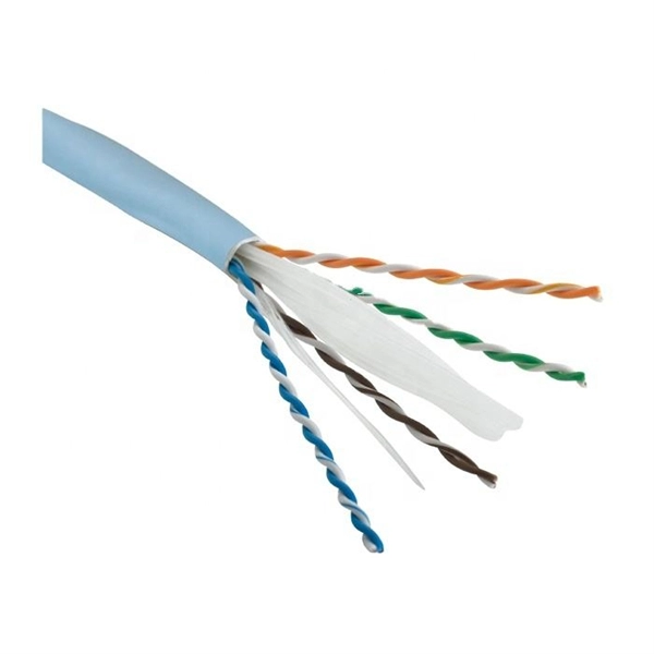
This article outlines five specific steps for repair: 1) Identify the break; 2) Cut out the damaged section; 3) Strip the cable; 4) Trim the fiber ends; 5) Test the repair. DIY fiber optic cable repair kits are increasingly popular for those who prefer home repairs. This guide covers the essential tools and step-by-step procedures for low-loss fiber optic cable repair. Construction Activities: Accidental damage during construction. While a cut or damaged fiber optic cable can temporarily take your network down, it is possible to quickly fix the cable with the right tools. This wikiHow article will teach you how to splice a cut fiber optic cable back together with a fiber optic stripper and cutter and a fiber optic crimper. These cables consist of a core (glass or plastic) that carries light signals, surrounded by cladding to reflect light inward, a buffer for protection, and an outer jacket for durability. The actual steps may vary depending on the cable and/or connectors. Fiber optic cables are typically damaged in one of two ways: A premade fiber optic cable suffers connector damage when too. Don't let cable woes ruin your streaming binge or video conference; instead, explore these six proven ways to troubleshoot and fix your optical cable issues. Before diving into solutions, it's crucial to understand what an optical cable is and how it works. Begin by identifying the damage, which can be done using an Optical Time Domain.
[PDF]
An optical power meter (OPM) is a device used to measure the power in an signal. The term usually refers to a device for testing average power in systems. Other general purpose light power measuring devices are usually called,, power meters (can be sensors or ), or lux meters. A typical optical power meter consists of a , measuring and display. The sens.
[PDF]

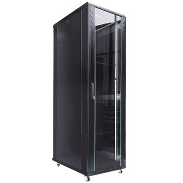
First, connect each pre-terminated fiber optic cable to the adapter panel separately, making sure the ports correspond one-to-one; then fix the fiber optic adapter panel to the front panel of the distribution box with the bend radius control clip. In general, installing the optical fiber distribution box can be divided into three steps: installing the optical fiber distribution box on the rack, introducing the optical cable into the optical fiber distribution box, and planning the optical fiber path in the optical fiber distribution box. The. Bottom installation: Select a proper installation position in the equipment room and drill four holes in the floor according to the dimensions shown in the manual. Fix the rack to the ground with expansion bolts. Top installation: Dimensions of four connection holes on the top according to the. The Optical Distribution Box (ODB) is high-density 2-in-2-out fiber box solution. Designing with a compact size of 340x220x100mm, the cabinet accommodates 1x2,1x4,1x8 and 1x16 etc. The 4 ports are sized for main cable from 9 to 16mm in diameter, along with 16 3mm cables. Accessory Kits:. Install the optical fiber distribution box on the rack. Ensure that the box is installed firmly and horizontally, and the deviation of perpendicularity is not greater than 3mm.
[PDF]

Abstract:The design, installation, and protection of wire and cable systems in substations are covered in this guide, with the objective of minimizing cable failures and their consequences. In modern electrical systems, cable distribution boxes (also known as electrical distribution boxes or distribution boxes) play a crucial role as the key hub for managing, distributing, and protecting circuits. Whether it is residential buildings, commercial facilities or industrial sites, the. The power demanded in electricity systems also determines the cable cross-section and properties as well as the current to be transferred. In case of high power use, to meet the demand of currentAnd in order for the current to be carried at the demanded high powers to be met, the method of parallel. A distribution box is the heart of any electrical system. It takes the incoming power and safely distributes it to different circuits throughout your building. Whether in a home or an industrial facility, this box keeps your electrical setup organized, functional, and efficient. However, the key to. Distribution Board or DB is an electricity supply system or a common enclosure that distributes the electrical power feed into subcircuits. Armored Cable (Type AC). Armored cable is an assembly of insulated conductors, 14 AWG through 1 WG, wrapped with waxed paper. The conductors are contained within a fl exible spiral metal (steel or al minum) sheath that the edges.
[PDF]

To set up your router for fiber internet quickly, connect the router to your fiber modem, access the router's settings via a web browser, and input the provided ISP credentials. Make sure to update the firmware, configure Wi-Fi security, and customize your network name for. However, setting up a fiber optic connection to your router can seem daunting if you're unfamiliar with the process. In this guide, we'll walk you through how to connect a fiber optic cable to a router safely and efficiently. Why Use Fiber Optic Internet? Before diving into the setup, let's quickly. The process to connect fiber optic cable to router requires careful attention to detail, but I'll walk you through every critical step with the precision and clarity you deserve. This comprehensive guide combines industry standards with field-tested practices to ensure you achieve a rock-solid. Sharing an internet connection with your neighbor isn't uncommon—especially in places where homes are joined wall-to-wall. Whether you're living in a duplex, a townhouse, or a multi-unit apartment complex, the idea of splitting the cost of internet service and maximizing bandwidth efficiency. Setting up a fiber internet connection requires understanding key hardware components and following a specific connection sequence to establish your home network. The fiber. Setting up your fiber router correctly ensures you get the most from your connection.
[PDF]
