Discover 29 Transimpedance Amplifiers manufacturers and distributors on GlobalSpec. Find products, technical articles, videos, and more. The MAX3744/MAX3745 transimpedance amplifiers pro-vide a compact, low-power solution for communication up to 2. They feature 330nA input-referred noise at 2. 1GHz bandwidth (BW) with 0. Please view our selection of transimpedance amplifiers below Smart. Mignal offers a portfolio of high performance Silicon Germanium (SiGe) and commercial CMOS transimpedance amplifiers providing wideband width, low noise, low power, and guaranteed quality and reliability. Mignal's family of TIA products provide users with right set of features including plenty of. The Relevance Inspector will open in the Coveo Administration Console. Maxim Integrated Products is a publicly traded company that designs, develops, and sells a wide range of high-performance analog and mixed-signal integrated circuits (ICs). The company was founded in 1983 and is headquartered in San Jose, California. Maxim Integrated Products serves customers in a. This section provides an overview for transimpedance amplifiers as well as their applications and principles.
[PDF]

It operates by splitting incoming light into one or two beams, with one or more beams passing through the optical element and one or more beams being redirected at an angle away from it. This tool is crucial for various applications, including lasers, heads-up displays, and other. Beamsplitters are fundamental components in optical engineering, serving to precisely divide a single input beam of light into two distinct output beams. This division allows for the simultaneous analysis or utilization of the light's properties along two separate paths. It is a crucial part of many optical experimental and measurement systems, such as interferometers, also finding widespread application in fibre optic telecommunications. In its. Beamsplitters are optical devices able to either split an incident light beam into two separate beams or combine two incoming beams from distinct angles into a single output. These versatile tools can split both laser and regular light, depending on the application in question. Image Credit: Shanghai Optics Most plate beamsplitters are. Explore the precision, applications, and design principles of beam splitters, essential for advancements in scientific research and technology. Beamsplitters are often classified according to their construction: cube or plate.
[PDF]
Semiconductor optical amplifiers (SOAs) are amplifiers which use a semiconductor to provide the gain medium. These amplifiers have a similar structure to but with anti-reflection design elements at the end faces. Recent designs include anti-reflective coatings and tilted and window regions which can reduce end face reflection to less than 0.001%. Since this creates a loss of power from the cavity which is greater than the gain, it prevents the amplifier from acting as a laser.
[PDF]

FTTP ONT red light often indicates optical signal loss or fiber cable connection issues. First, check the fiber optic cable for bends, damage, or loose connections at the. An optical audio cable should have a red light at each of the connectors when it's in place and working correctly. If you don't see the light at either of the ends, the cable isn't connected properly, is broken, or you might just have a faulty cable. The light is an indicator of a problem, rather. Customer: The power light is green, the optical light is red, and the UNI-D 1 port is orange. Credit: Jim Gensheimer for Stanford University Light does a lot of work in the modern world, enabling all types of information technology, from TVs to satellites to fiber-optic cables that carry. An optical amplifier is a device which receives some input signal light and generates an output signal with higher optical power. Typically, inputs and outputs are laser beams (very rarely other types of light beams), either propagating as Gaussian beams in free space or in a fiber. The. An optical amplifier is a device that amplifies an optical signal directly, without the need to first convert it to an electrical signal. I'm just wondering because I had a fiber optic cable plugged in and pulled it out while using it and just hoping that didn't cause some issue. Most optical outs are.
[PDF]
This occurs because when s-polarized light hits the reflecting surface, the electric field is in the same plane as the surface. The set up is either: Camera lens - beam splitter - camera x2 Or, Beam splitter - (lens + camera) x2 I want to be able to take 2x photos at once, so the light has to go through the beam splitter. I used the polarised flexible sheet as a proof on concept, which worked but need to make it more. A beam splitter or beamsplitter is an optical device that splits a beam of light into a transmitted and a reflected beam. It is a crucial part of many optical experimental and measurement systems, such as interferometers, also finding widespread application in fibre optic telecommunications. Additionally, beamsplitters can be used in reverse to combine two different beams into a single one. The resulting beams are directed along different paths, allowing a single light. 📦 For purchasing, use the RP Photonics Buyer's Guide for beam splitters. It provides an expert-curated supplier directory, buyer-focused technical background information, and structured selection criteria to support professional procurement decisions. What are Beam Splitters? A beam splitter (or. am Splitters/Combiners. This document describes this product line, as well as general operation guidel into two output beams t beams of equal power. The standard product is designed for use in the visible spectrum 400-700 nm wavelength). The cube can only be effectively used as a splitter; used.
[PDF]

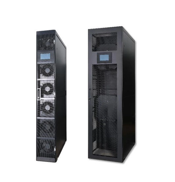
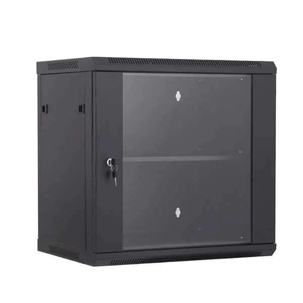
They function as intermediate distribution points between: The enclosure itself does not process optical signals. Its role is structural and operational rather than active transmission control. Different box structures support different deployment layers inside FTTH and. In the complex architecture of fiber optic networks, the Optical Distribution Frame (ODF) serves as the linchpin for organizing, protecting, and distributing optical signals. Whether in data centers, telecom central offices, or enterprise network rooms, ODFs enable efficient fiber management. A Fiber Optic Distribution Box is a key device in fiber optic communication networks, used for centralized management, distribution, and protection of fiber optic connections. As an important node in fiber optic access networks (such as FTTH) and backbone networks, it ensures efficient transmission. An optical distribution frame (ODF) is a crucial component in the telecommunication industry, specifically in the area of fiber optic networks. Its role is structural and. This complete guide explores everything you need to know about ODFs — from their structure, types, and key components, to installation best practices and modern design trends. It serves as a merging point for the optical fibers, where connections are consolidated and routed, thus minimizing signal attenuation. The ODF includes.
[PDF]

At its core, an overcurrent relay operates on a very simple concept: detect excessive current, then trip fast and isolate the fault. When current surpasses the relay's pickup setting, an internal mechanism triggers the circuit breaker. IEEE/IAS/I&CPSD Protection & Coordination WG Chair Jacobs Canada, Calgary, AB rasheek. com IEEE Southern Alberta Section PES/IAS Joint Chapter Technical Seminar - November 2016 Protective Relays - Technical Seminar Nov 2016 - Copyright: IEEE 2 Abstract: Protective relays and devices. Relay protection against high current was the earliest relay protection mechanism to develop. From this basic method, the graded overcurrent relay protection system, a discriminative short circuit protection, has been formulated. Types of over current relay. It is really current monitoring relay. Overcurrent Relay Definition: An overcurrent relay is a protective device that operates solely based on current without the need for a voltage coil. These relays are known for their speedy operation during a fault and are hence used widely in high-voltage applications. Let's know in. The Art and Science of Protective Relaying, by C. Mason, John Wiley and Sons, 1956. Evaluation of Distribution System Relaying Methods, by A. McConnell, Presented at the Pennsylvania Elec-tric Association, May 16-17, 1957.
[PDF]
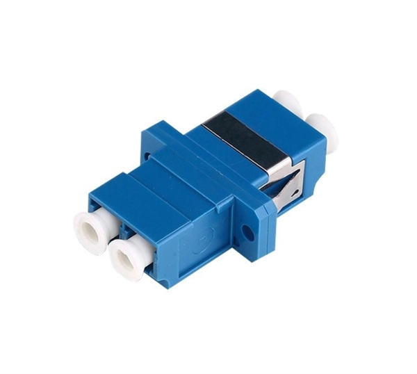
In this guide, you will find a chronological description of the fusion splicing process, the principal technical standards, and answers to the real-life questions network engineers and procurement teams may have. 📦 For purchasing, use the RP Photonics Buyer's Guide for fusion splicers. It provides an expert-curated supplier directory, buyer-focused technical background information, and structured selection criteria to support professional procurement decisions. This article explains the principle of fusion. Fusion splicers play a crucial role in the field of optical fibre communications by enabling the permanent bonding of two strands of glass fibre to create a continuous pathway for light to travel through. This process is achieved through precise alignment and fusion of the fibre ends using an. Fusion splicing is the process of fusing or welding two fibers together usually by an electric arc. Fusion splicing is the most widely used method of splicing as it provides for the lowest loss and least reflectance, as well as providing the strongest and most reliable joint between two fibers. Each splicer is equipped with a cleaver and stripper, conveniently includes in a single case. The goal is to align the microscopic glass cores (typically.
[PDF]
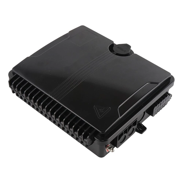
A fiber terminal box, also known as a fiber distribution box, is a device used in fiber-optic communication networks to terminate, splice, and distribute optical fibers. It is a small enclosure that can house and protect the fiber optic cables, splices, and connectors. Distribution boxes, terminal boxes, and closures are often compared because all three appear as fiber aggregation or transition points within a physical network. In diagrams and BOMs, they are frequently grouped under “fiber boxes,” leading to the assumption that they differ only in form factor or. A terminal block box, also known as a junction box or distribution box, is a closed or semi-closed enclosure that contains terminal blocks (usually in the form of screw-type, spring-type or peel-free type). Its core function is to provide a centralized connection, distribution, transfer and. A Fiber Access Terminal (FAT), also known as a Fiber Access Terminal Box (ATB) or Fiber Distribution Terminal (FDT), is a key component found in optimized fiber optic access networks for FTTH implementations. The fiber termination box.
[PDF]
