Optical power meters can measure the power of both single-mode and multimode fibers. In single-mode fiber, the rays travel down its entire length without any internal reflection at all. In multimode fiber, multiple rays enter at different angles and possibly have different wavelengths. An optical power meter (OPM) is a device used to measure the power in an optical signal. The term usually refers to a device for testing average power in fiber optic systems. The term "optical power meter" may sound generic, but in popular usage, it specifically implies a fiber optic power meter. For light power measurements outside the field of. Optical loss is measured in “dB” which is a relative measurement, while absolute optical power is measured in “dBm,” which is dB relative to 1mw optical power Loss is a negative number (like –3. It details the main components, including sensor heads and display units, and explains the two primary sensor technologies: robust thermal sensors for high powers and. The OMM-6810B is a power and wavelength meter capable of simultaneously measuring the optical power and wavelength of a laser source. A wide variety of measurement heads cover wavelength ranges from 400 to 1650 nm for power ranges of up to +40dBm or 10W. Fiber optic connections form the backbone of modern data infrastructure, yet even a small speck of dust can render a link completely.
[PDF]
An optical power meter (OPM) is a device used to measure the power in an signal. The term usually refers to a device for testing average power in systems. Other general purpose light power measuring devices are usually called,, power meters (can be sensors or ), or lux meters. A typical optical power meter consists of a , measuring and display. The sens.
[PDF]
Multimode fiber optic cable has a larger core, typically 50 or 62. 5 microns that enables multiple light modes to be propagated. Because of this, more data can pass through the multimode fiber core at a given time. The maximum transmission distance for MMF cable is around 550m at the speed of. Multimode Fiber (MMF) has a core diameter, typically 50–100 micrometers, has ability to transfer multiple modes of light through the fiber core, uses lower-cost electronics (LED, VCSEL) operates at the 850 nm and 1300 nm wavelength and is used for short distance interconnections (up to 550m). This Applications Engineering Note (AE Note) discusses the criteria for properly selecting the optimal multimode fiber (MMF) for enterprise applications. Both fiber types play essential roles in today's optical.
[PDF]

Shop DigiKey's large in-stock selection of Fiber Optic Attenuators. View inventory, pricing and order now for same day shipping!. Use this optical attenuators buying guide to compare major types, define selection criteria, and find suppliers: 🔬 Encyclopedia article: optical attenuators 📦 Top-level product category: optical components and devices Click on a logo to get to the details of that supplier's offer. Our list of. Keysight optical attenuators provide precise control of optical signal power for accurate and repeatable optical component testing. Attenuators emulate signal loss, balance power levels, and protect sensitive devices during testing. Keysight attenuators offer low insertion loss, low. Attenuators from VIAVI offer a complete range of power-balancing options, from fixed to variable optical attenuators in field, lab, and manufacturing environments. VIAVI offers the industry's most complete range of optical attenuators for installation and maintenance of singlemode and multimode. Fiber optic attenuators are devices used to reduce or monitor the power level of a fiber optic signal. Basic types of fixed attenuation include single mode, dual window and multimode in D4/PC, FC, FC/UPC, MU, SC, SC/APC and UPC, ST and ST/UPC style connectors. Optical attenuators usually work by. FS fixed and variable fiber optic attenuators with leading attenuating fibers guarantee consistent and stable fiber attenuation (0~60dB) in WDM transmission.
[PDF]

A fiber optic pigtail is a short segment of optical fiber cable (typically 0. 5–3 meters, though custom lengths reach 10 meters) that is factory-terminated with a connector on one end only. This design allows for quick and easy splicing to another fiber or cable, ensuring a secure and efficient connection. Ideal for use in. Fiber Optic Pigtails 900um - 1m, 2m, and 3m lengths - Order now! Reliable fiber optic pigtails with zirconia ceramic ferrule & Corning fiber cable. Available in various lengths and connector styles. Buy Now. Usually ships within 24 hours. The quality of the components used to build our fiber. These 900µm Tight Buffer pigtails are designed for high fiber count splicing applications and are color coded to TIA-598-A industry standards for ease of use. All pigtails feature low insertion. The Relevance Inspector will open in the Coveo Administration Console. The pigtails are available separately or in kits for ease of installation and. In the precision-driven world of fiber optic networking, where every decibel of loss and every reflection matters, the fiber optic pigtail stands as one of the most critical yet often underappreciated components.
[PDF]
State Trading Organization PLC. State Trading Organization PLC. Pre-designed kitchen units available in stock. Fast delivery and quick installation options. Fully customizable kitchen setup based on your space and needs. Includes consultation, planning, and product selection. Need Help? Please call us at: 3316464 | 7976464 | 7976464 Discover TVs, ACs. uxcellFiber Optical Power Meter with Light Source SC FC Connector Optic Test Equipment for CCTV Communication Engineering -70 to 10 dBm What is Desertcart? Is it safe to order from?+ Very impressed with the quality and fast delivery. Will shop here again. Best international shipping I've ever. Optical power meters and detectors have been served by Newport for over 30 years. The offering ranges from a low cost, hand-held meter to the most advanced dual channel benchtop power meter available in the market. Our 1936-R/2936-R series boasts state-of-the-art analog boards with a whopping 250. Our Supply Chain division creates custom solutions for enterprise-sized organizations. Discover what makes DHL Supply Chain the perfect fit as your outsourced logistics provider (3PL). Use our shipping calculator to instantly estimate shipping costs for packages or pallets, domestic and. © All rights reserved. State Trading Organization PLC. FS offers a range of fiber optic power meter, choose from a variety of cost-effective optical power meters. Money Back Guarantee.
[PDF]
Connect the red wire to the copper wire with the red color bar of the optical/electrical composite cable, and connect the black wire to the other copper wire of the optical/electrical composite cable. Then press and secure the crimp tube. Ensure that no copper. The composite fiber optic cable is a type of cable that combines both fiber optic and copper conductors within a single cable sheath. This hybrid construction allows for the simultaneous transmission of data using fiber optics and electrical power or additional data using copper conductors. How to Use the Composite Fiber Optic Cable? To begin, you need to gather all the accessories and equipment required: 1. Waterproof Industrial-Grade Fiber PoE Media Converter Compatible with the IEEE802. Cut the cable along the center and pull one copper cable on the left and right sides to the position shown in the figure to expose the optical fiber. Whether you're a seasoned technician or a beginner, this guide has something for everyone. more In this video, we'll walk you. In a previous blog, we covered what to do when you need to connect a device that is located beyond the 100-meter distance requirement and described four ways to address the problem—a new TR, the use of an extender device, extended-reach copper cable and fiber. This article will guide you through the necessary tools, materials, and methods on how to connect fiber optic cables effectively.
[PDF]

The mechanical dimensions of an optical power sensor can be quite relevant for applications, e.g. when a sensor needs to be temporarily inserted into some beam path, where there is little available space. There are some very flat hand-he. The mechanical dimensions of an optical power sensor can be quite relevant for applications, e.g. when a sensor needs to be temporarily inserted into some beam path, where there is little available space. There are some very flat hand-held sensors, mostly based on photodiodes, which require quite little space. Thermal power sensors are intrinsically relatively slow – particularly those for high powers, where the thermal capacity of the sensor is tentatively higher. Typical response times are of the order of 0.2 s to 2 s. Even photodiode-based power meters are normally not made very fast, since one could anyway not read a display which is updated e.g. 10. Power meters require some electrical power, which may either be provided with an external power supply or with batteries (which are normally rechargeable). Battery-powered operation is of course convenient by eliminating another cable enter the requirement of a nearby power socket, but on the other hand the need for regular recharging can also be i.
[PDF]

Optical fiber cables consist of several key components, including the core, cladding, coating, strengthening fibers, and outer jacket, each essential for effective data transmission. Communication optical cable is a common wiring product. You should choose according to the nature of the specific project. Communication cable structure cable core Cable core: It is located in the center of the optical cable and. A TOSLINK optical fiber cable with a clear jacket. These cables are used mainly for digital audio connections between devices. A fiber-optic cable, also known as an optical-fiber cable, is an assembly similar to an electrical cable but containing one or more optical fibers that are used to carry. An optical fiber cable is a complex structure designed to protect fragile glass fibers that transmit digital data using light signals. This advanced cabling solution allows fast, secure data transfer and telecom over long distances. Understanding the components within a fiber optic cable enables. This series of courses are based on the Navy Electricity and Electronics Training Series (NEETS) section on Fiber Optic cable systems. The NEETS series is produced by the Naval Education and. This Lesson Learned is based on Maintainability Technique number OPS-08 from NASA Technical Memorandum 4628, Recommended Techniques for Effective Maintainability. It then discusses the history of optical fibers and their structure.
[PDF]

The receiver of an optical module has an overload point. Therefore, an optical attenuator is required to reduce the optical power. By introducing a precise and constant amount of optical loss, it ensures that the incoming signal remains within the optimal operating range of the receiver. A. Average optical power refers to the optical power outputted by the optical module's transmitter under normal working conditions, which can be understood as the intensity of light. The transmitted optical power is related to the proportion of "1"s in the transmitted data signal; the more "1"s, the. The receiver of an optical module has an overload point. If the optical power received by the receiver is excessively high, the optical module will be burnt. In addition, during signal transmission in a WDM system, the. 📦 For purchasing, use the RP Photonics Buyer's Guide for optical attenuators. It provides an expert-curated supplier directory, buyer-focused technical background information, and structured selection criteria to support professional procurement decisions. Optical attenuators are devices that. An optical attenuator, or fiber optic attenuator, is a device used to reduce the power level of an optical signal, either in free space or in an optical fiber. Optical internetworks are data networks composed of routers and data.
[PDF]
Commonly, a power meter on its own is used to measure absolute optical power, or used with a matched light source to measure loss. When combined with a light source, the instrument is called an Optical Loss Test Set, or OLTS, typically used to measure optical power and end-to-end optical loss.OverviewAn optical power meter (OPM) is a device used to measure the power in an signal. The term usually refers to a device for testing average power in systems. Other general purpose light power measuring. The major types are (Si), (Ge) and (InGaAs). Additionally, these may be used with attenuating elements for high optical power testing, or wavelengt. A typical OPM is linear from about 0 dBm (1 milli Watt) to about -50 dBm (10 nano Watt), although the display range may be larger. Above 0 dBm is considered "high power", and specially adapted units may measure u.
[PDF]
An optical power meter (OPM) is a device used to measure the power in an signal. The term usually refers to a device for testing average power in systems. Other general purpose light power measuring devices are usually called,, power meters (can be sensors or ), or lux meters. A typical optical power meter consists of a , measuring and display. The sens.
[PDF]

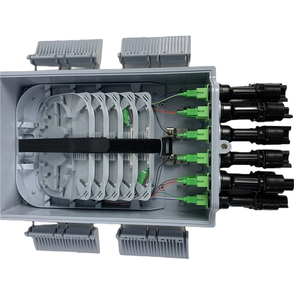
Enter the optical input power, additional loss, and select a PLC splitter or tap ratio to estimate the output power (in dBm) on each branch. Optical splitters play a crucial role in Fiber to the Home (FTTH) Passive Optical Network (PON) systems, efficiently distributing a single optical signal to multiple destinations. The split ratio and insertion loss are two key parameters defining their performance. A deeper understanding of these. In the backbone of modern Fiber-to-the-Home (FTTH) networks, optical splitters serve as the unsung heroes that enable cost-efficient connectivity for millions of subscribers. By dividing a single optical signal from a central Optical Line Terminal (OLT) into multiple outputs for Optical Network. Optical splitters play an important role in FTTH PON networks where a single optical input is split into multiple output, thus allowing a single PON interface to be shared among many subscribers. The optical splitters have no active electronics and don't require any power to operate. The optical power at the input is split to the outputs at an even ratio: Optical splitter modules use passive optical circuits. The modules fit the OG3-FR frame but draw no.
[PDF]