Passive receiver that captures an optical signal on a single fiber (1310/1490/1550nm), and demultiplexes it (WDM). The TV signal (1550nm) is converted to an RF output (54-2400MHz), while the 1310/1490nm wavelengths are destined to data signals (GPON) to distribute them through. Facilitates rapid deployment and hassle-free replacement. Contributes to wide coverage and supports multiple optical nodes, facilitating network upgrade and expansion effortlessly. Maintains stable output with minimal gain fluctuation (±0. 5dB) and low noise signature (≤5. Supports. REF. This FTTH WDM Passive Optical Receiver is engineered for high-performance fiber-to-the-home networks. It features a passive design that operates without an external power supply, simplifying installation and reducing maintenance. With integrated WDM technology, it efficiently handles 1310nm/1490nm. Passive FTTH Optical receiver, cost-effective, no need power. ■ High quality plastic case; ■ Digital signal input -10dBm, analog signal input -7dBm; ■ Without power supply and consumption; ■ SC/APC or FC/APC; ■ Output level> 64dBuV (Pin=0dB).
[PDF]

Enter the optical input power, additional loss, and select a PLC splitter or tap ratio to estimate the output power (in dBm) on each branch. Optical splitters play a crucial role in Fiber to the Home (FTTH) Passive Optical Network (PON) systems, efficiently distributing a single optical signal to multiple destinations. The split ratio and insertion loss are two key parameters defining their performance. A deeper understanding of these. In the backbone of modern Fiber-to-the-Home (FTTH) networks, optical splitters serve as the unsung heroes that enable cost-efficient connectivity for millions of subscribers. By dividing a single optical signal from a central Optical Line Terminal (OLT) into multiple outputs for Optical Network. Optical splitters play an important role in FTTH PON networks where a single optical input is split into multiple output, thus allowing a single PON interface to be shared among many subscribers. The optical splitters have no active electronics and don't require any power to operate. The optical power at the input is split to the outputs at an even ratio: Optical splitter modules use passive optical circuits. The modules fit the OG3-FR frame but draw no.
[PDF]

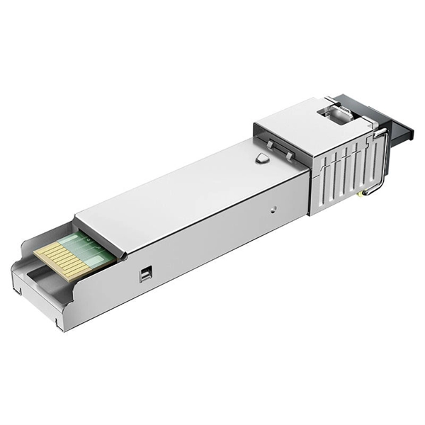
The transmitter optical power ranges from +3 to +7 dBm, while receiver sensitivity reaches -30 dBm, supporting distances up to 20 kilometers over standard single-mode fiber infrastructure. Note 1: Measured with 1310nm, 1. 244Gbps PRBS223- 1 burst-mode optical input, ER= 10dB, BER= 1x10⁻¹⁰; Single burst packet length is 40us and packet interval is 40us. Note 2: Input optical power level difference of adjacent burst packets. Note 3: Receiver optical power ranged from -8dBm to -28dBm. designed for FTTH GPON applications. Packaged in a Small Form- infrastructure in edge, enterprise, or distributed environments. robust fiber-to-the-home (FTTH) or small-scale fiber deployments. temperature, voltage, bias current, and optical power. On the uplink side, it operates. Max. Supporting 20km over single-mode fiber with 1490/1310nm wavelengths, this module delivers 33 dB link budget for 1:64 or 1:128 split ratios at 2. 488 Gbps downstream and 1. SC/PC connector for OLT PON port integration. Complete technical specifications and product details Our. Cisco ME Series products support any fiber-based (FTTx) access scenarios, including Fiber To The Home (FTTH), Fiber To The Building (FTTB), Fiber To The Curb (FTTC), Fiber To The cell (FTTc), and Fiber To The business (FTTb). Figure 1 illustrates the Cisco GPON solution. The Cisco GPON. The following tables list the performance specifications for the various functional blocks of the integrated optical transceiver module.
[PDF]
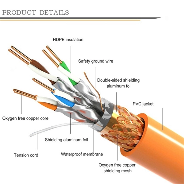
Fiber Breakage: Single-mode fiber optic cables can be prone to fiber breakage, which can result in signal loss. Fiber breakage can occur from physical damage, such as bending or crushing the cable. This can cause signal attenuation and may even result in signal loss. To avoid bend loss, it is important to follow the minimum bend radius specified by the cable manufacturer. NEATEL's The Single-Mode (SM) Breakout Indoor Fiber Cable is designed for high-performance, secure fiber optic connectivity in indoor environments. Unlike tight-buffered fiber cables, this breakout-style cable features multiple individually reinforced sub-cables (typically 2. Tension and stress: Fiber optic cables can be damaged if they are subjected to too much tension or stress, as this can cause the fibers to break. Fiber design and transmission technology have collaboratively evolved to increase bandwidth. Dig-ups dominate! Cablers have very little influence on the majority of causes of cable field failures. While a small percentage, we can examine the “intrinsic” cable failures and what is done to prevent. Recommendation ITU-T L. 103 describes characteristics, construction and test methods for optical fibre cables for indoor applications. In order for an optical fibre to perform appropriately, characteristics that a cable should have been described. Also, the method of determining whether the cable.
[PDF]

This paper is focused on the performance analysis of protection mechanisms utilized in common wavelength division multiplexing-based passive optical networks. Wavelength division multiplexers are fundamental to the functioning and performance of integrated photonic circuits, with applications ranging from optical interconnects to sensing and quantum technologies. Current solutions are limited by trade-offs between channel spacing, crosstalk, insertion. Wavelength division multiplexing (WDM) is a technology for increasing the transmission capacity of optical fiber communications by sending multiple data channels simultaneously through a single fiber, each on a different wavelength of light. The main aim of the proposed research is providing an option of comparing different traffic protection scenarios for advanced optical. Herein, an attention-grabbing and up-to-date review related to major multiplexing techniques is presented which includes wavelength division multiplexing (WDM), polarization division multiplexing (PDM), space division multiplexing (SDM), mode division multiplexing (MDM) and orbital angular momentum. The journey of optical multiplexing began in the 1970s with the introduction of Wavelength Division Multiplexing (WDM), which revolutionized the capacity of optical communication systems. The primary objective of optical multiplexing has been to maximize the utilization of available bandwidth in.
[PDF]

This paper will review the development of fiber-optic high-temperature sensors over the last 30 years, presenting their design and fabrication methods according to sensing type and typical temperature measurement performance. The full paper consists of eight sections. Fiber-optic high-temperature sensors are gradually replacing traditional electronic sensors due to their small size, resistance to electromagnetic interference, remote detection, multiplexing, and distributed measurement advantages. This paper reviews the sensing principle, structural design, and. Luna's Optical Backscatter Reflectometer (OBR) products are based on OFDR and provide a level of detail and precision not available with the prevailing fiber optic diagnostic tool - the optical time domain reflectometer (OTDR). OBR systems map out loss along a single-mode fiber (SMF) or multi-mode. breadth and most comprehensive solutions for optical communications test products to be found in one place. Corning's High Temperature Fibers are designed for applications requiring improved fatigue resistance, high usable strength, and excellent resistance to higher temperatures and hydrogen permeation. Thus, wireless communication -situ processing of data would combined with in significantly improve the ability to include sensors into high temperature systems and thus lead toward more intelligent engine systems. NASA Glenn Research Center (GRC) is presently lea, communication systems,ding the.
[PDF]
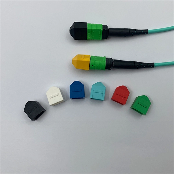
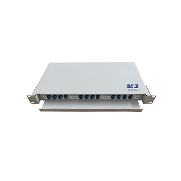
IEC fiber connector standards establish the global specifications for connector geometry, mating interfaces, optical performance classes, and mechanical testing across all fiber network environments. Optical connectors are used to connect optical devices to other optical devices or systems. However, each connection introduces a certain amount of insertion and return loss that. Connectors play an important role in Enterprise network architecture. They give you the power to add, drop, move, and change the network. is a small cylinder used to mount. The Fischer FiberOptic Series offers robust and faultless optical performances in any conditions. Combined with easy use, cleaning and maintenance. Tested for harsh and extreme environments (Norm IEC 61753-1 Cat. These standards ensure that passive fiber-optic components remain interoperable, stable, and. designed for diverse fiber optic applications. But what exactly sets a fibe optic connector apart in terms of its merits? The primary purpose of a fiber optic connector is to terminate the ends of fiber optic cables, ensuring they can be int rconnected reliably with minimal optical loss. After. Fiber optic technology is used in ever-increasing applications due to its inherent advantages (lower weight, EMI/RFI immunity, higher bandwidths and distances) over copper. There are many.
[PDF]

In this paper, various operational factors affecting 100G transmission over G. D fiber-cables are discussed to make the right fiber selection for the long-haul network. Selecting appropriate G. 652 fibre was originally optimized for use in the 1310 nm wavelength region but can also be used in the 1550 nm region. This is the latest revision of a Recommendation that was first created in 1984 and deals with some relatively minor modifications. a number of concatenated cable. G. 92% of. Fiber optic cables are the ultimate technology used in data transfer using light waves. They are classified based on wavelength band, core/cladding size, application, and compliance with international standards such as IEC, ITU-T, and TIE/EIA. In the next sections, the real artwork is putting on. This guide explains the most important ITU-T G. 655—to help you make an informed decision for your project, whether it's a long-haul backbone or a final FTTH drop. In the world of fiber optics, not all glass is created equal. The core of every cable—the optical. Because GPON and XGS-PON are deployed in diverse environments, fiber-containing components such as PLC splitters must be evaluated not only by their standard parameters but also by their sensitivity to bending loss, which is critical for maintaining stable optical transmission. The ITU-T defines.
[PDF]
Optical splitters play a crucial role in Fiber to the Home (FTTH) Passive Optical Network (PON) systems, efficiently distributing a single optical signal to multiple destinations. The split ratio and insertion loss are two key parameters defining their performance. Understanding Fiber Optic Splitters: Principles, Parameters, Types, Applications, and Future Trends 1. Introduction Fiber optic splitters are integral components in the world of optical networks. A deeper understanding of these. 📄 What is an Optical Splitter? An Optical Splitter, also known as a beam splitter, is a passive optical device that divides a single input optical signal into two or more output signals. Conversely, it can also combine multiple signals into one. Its primary role is in Passive Optical Networks. Bandwidth is shared amongst customers in a PON, and the bandwidth received by a customer is not related to the power received at the optical network terminal (ONT) as long as the power is high enough so the ONT can operate. Their ability to efficiently manage optical signals makes them indispensable in various. The performance of optical beam splitters can significantly influence the overall performance of laser-based instrumentation and measurement systems. This paper examines two of the most critical performance factors: optical efficiency and wavefront distortion. Efficiency is a function of both the.
[PDF]

An optical receiver is an electronic device that detects and converts optical signals into electrical signals. The primary function of an optical receiver in digital TV setups is to facilitate the transmission of high-quality audio signals between. In this architecture, optical fiber carries signals from the headend to distribution nodes across long distances, after which coaxial cable completes the final delivery to subscribers. He oversaw the day-to-day operations of the site to ensure readers have the most up-to-date information on everything from operating systems to gadgets. Prior to his current. othing beats surround sound for movies and TV — and surround sound starts with a home theater receiver. But a receiver can give you a lot more than that. During my time as a Crutchfield Sales Advisor, I helped many people choose the receiver that worked best for them. They are a step above the previously used analog audio outs. The most common types are optical and coaxial. The rest of this article will delve into how digital audio output works, how its types differ, and. When it comes to enhancing your home entertainment experience, connecting your optical TV cable to your home theater system is an essential step that can significantly elevate your audio-visual enjoyment. This guide will walk you through the process in detail, ensuring that you have all the.
[PDF]
It plugs into network equipment (like switches, routers, or servers) and its primary function is to convert electrical signals from the device into light signals for transmission over fiber optic cables, and then convert received light signals back into electrical signals. People can also refer to an optical transceiver as a fibre optic transceiver or optical module. A transceiver is a mix of the words 'transmitter' and 'receiver. ' An optical transceiver includes an optical. This section explains the core IP and optical components used in traditional hierarchical networks. It helps readers understand the router, transponder, ROADM, amplifier, and management elements that form the baseline network architecture. In fiber optics, this data is sent in the form of pulses of light over an optical fiber, at very high speeds and across long distances. Essentially, these devices. Why choose Nokia for your optical network? The Nokia industry-leading optical network portfolio leverages highly vertically integrated coherent optical engines and includes the latest generation of open and flexible optical line systems, intelligent coherent pluggables, ultra power-efficient. This page provides an introduction to optical wireless networks. It compares short-range (directed and diffused) and long-range optical wireless technologies, highlighting their differences. The broadband wireless.
[PDF]
Mouser ofrece inventarios, precios y hojas de datos para Receivers Transmisores, receptores y transceptores de fibra óptica. Shipment data shows what products a company is trading and more. Learn more Tecno Supplier S. BARRIO CONCEPCION SAN PEDRO SULA HONDURASC. CENTRO COMERCIAL SANTA ANITA LOCAL203 TEL. Find their customers, contact information, and details on 74 shipments. Compare products based on your own technical specification criteria. How does our search work? With MEET OPTICS search you get direct access to our database of thousands of optical components from providers worldwide. Prices and product specifications directly listed from optical component.
[PDF]
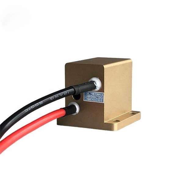
The zero-buoyancy rov cable was born as a power connection and control of underwater robot equipment, as well as signal transmission and feedback link cable applications. The zero-buoyancy cable has been tested by the market and practice due to its excellent. The global underwater zero buoyancy cable market is experiencing robust growth, driven by the expanding offshore energy sector, increasing demand for subsea infrastructure development, and advancements in underwater communication technologies. Linden Photonics is renowned for its innovative fiber-optic solutions, specifically designed for Remote Operated Vehicles (ROVs). These ROV tethers are crucial in underwater applications, offering high performance, durability, and reliability in challenging environments. For use with ROV's (Remote.. Customizable neutral buoyancy fiber optic power cable for ROVs and underwater drones. High‑performance hybrid design combining power and data in one composite cable. Engineered for seawater resistance, flexibility and subsea reliability. Suitable for inspection systems, subsea cameras and. At Invocean, we understand the increasing demands and the critical nature of Remotely Operated Vehicles (ROVs) in various industries such as underwater construction, surveillance, salvage, and scientific research. To support these high-performance tasks, ROVs and Micro-ROV's require reliable.
[PDF]