Optical power meters can measure the power of both single-mode and multimode fibers. In single-mode fiber, the rays travel down its entire length without any internal reflection at all. In multimode fiber, multiple rays enter at different angles and possibly have different wavelengths. An optical power meter (OPM) is a device used to measure the power in an optical signal. The term usually refers to a device for testing average power in fiber optic systems. The term "optical power meter" may sound generic, but in popular usage, it specifically implies a fiber optic power meter. For light power measurements outside the field of. Optical loss is measured in “dB” which is a relative measurement, while absolute optical power is measured in “dBm,” which is dB relative to 1mw optical power Loss is a negative number (like –3. It details the main components, including sensor heads and display units, and explains the two primary sensor technologies: robust thermal sensors for high powers and. The OMM-6810B is a power and wavelength meter capable of simultaneously measuring the optical power and wavelength of a laser source. A wide variety of measurement heads cover wavelength ranges from 400 to 1650 nm for power ranges of up to +40dBm or 10W. Fiber optic connections form the backbone of modern data infrastructure, yet even a small speck of dust can render a link completely.
[PDF]

The document discusses optical detectors used in fiber optic communications systems. It describes the functioning of PIN photodetectors and avalanche photodetectors (APDs). Their performance. An optital detector is a device that converts light signals into electrical signals, which can then be amplified and processed. Such detectors are one of the most important components of an optical fiber communcation system and dictate the performance of a fiber optic communication link. PIN Photodiode A PIN photodiode is a widely. Detectors perform the opposite function of light emitters. The most common detector is the semiconductor photodiode, which produces current in response to. It explains how these devices use optical fibers to measure quantities like temperature, mechanical strain, pressure, and vibrations by detecting changes in light propagating through the fiber. A central focus is on sensors based on fiber Bragg gratings, where the Bragg wavelength is sensitive to. Optical Power Meters: These devices measure the power of optical signals in fiber optic cables. This information helps in maintaining signal integrity and quality across the.
[PDF]
Multimode fiber optic cable has a larger core, typically 50 or 62. 5 microns that enables multiple light modes to be propagated. Because of this, more data can pass through the multimode fiber core at a given time. The maximum transmission distance for MMF cable is around 550m at the speed of. Multimode Fiber (MMF) has a core diameter, typically 50–100 micrometers, has ability to transfer multiple modes of light through the fiber core, uses lower-cost electronics (LED, VCSEL) operates at the 850 nm and 1300 nm wavelength and is used for short distance interconnections (up to 550m). This Applications Engineering Note (AE Note) discusses the criteria for properly selecting the optimal multimode fiber (MMF) for enterprise applications. Both fiber types play essential roles in today's optical.
[PDF]

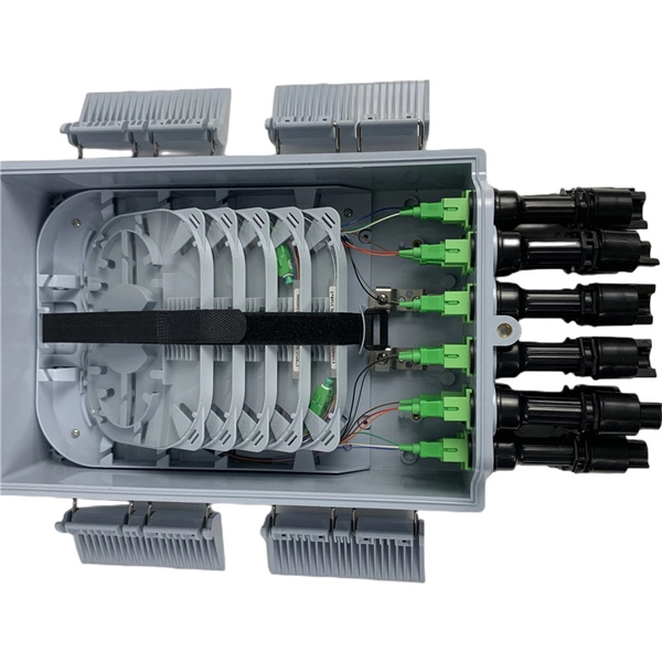
Enter the optical input power, additional loss, and select a PLC splitter or tap ratio to estimate the output power (in dBm) on each branch. Optical splitters play a crucial role in Fiber to the Home (FTTH) Passive Optical Network (PON) systems, efficiently distributing a single optical signal to multiple destinations. The split ratio and insertion loss are two key parameters defining their performance. A deeper understanding of these. In the backbone of modern Fiber-to-the-Home (FTTH) networks, optical splitters serve as the unsung heroes that enable cost-efficient connectivity for millions of subscribers. By dividing a single optical signal from a central Optical Line Terminal (OLT) into multiple outputs for Optical Network. Optical splitters play an important role in FTTH PON networks where a single optical input is split into multiple output, thus allowing a single PON interface to be shared among many subscribers. The optical splitters have no active electronics and don't require any power to operate. The optical power at the input is split to the outputs at an even ratio: Optical splitter modules use passive optical circuits. The modules fit the OG3-FR frame but draw no.
[PDF]

The mechanical dimensions of an optical power sensor can be quite relevant for applications, e.g. when a sensor needs to be temporarily inserted into some beam path, where there is little available space. There are some very flat hand-he. The mechanical dimensions of an optical power sensor can be quite relevant for applications, e.g. when a sensor needs to be temporarily inserted into some beam path, where there is little available space. There are some very flat hand-held sensors, mostly based on photodiodes, which require quite little space. Thermal power sensors are intrinsically relatively slow – particularly those for high powers, where the thermal capacity of the sensor is tentatively higher. Typical response times are of the order of 0.2 s to 2 s. Even photodiode-based power meters are normally not made very fast, since one could anyway not read a display which is updated e.g. 10. Power meters require some electrical power, which may either be provided with an external power supply or with batteries (which are normally rechargeable). Battery-powered operation is of course convenient by eliminating another cable enter the requirement of a nearby power socket, but on the other hand the need for regular recharging can also be i.
[PDF]
An optical power meter (OPM) is a device used to measure the power in an signal. The term usually refers to a device for testing average power in systems. Other general purpose light power measuring devices are usually called,, power meters (can be sensors or ), or lux meters. A typical optical power meter consists of a , measuring and display. The sens.
[PDF]
An increasingly common special-purpose OPM, commonly called a "PON Power Meter" is designed to hook into a live PON () circuit, and simultaneously test the optical power in different directions and wavelengths. This unit is essentially a triple power meter, with a collection of wavelength filters and optical couplers. Proper calibration is complicated by the varying duty cycle of the measured optical signals. It may have a simple pass/ fail display, to facilitate easy use by operators wit.
[PDF]
State Trading Organization PLC. State Trading Organization PLC. Pre-designed kitchen units available in stock. Fast delivery and quick installation options. Fully customizable kitchen setup based on your space and needs. Includes consultation, planning, and product selection. Need Help? Please call us at: 3316464 | 7976464 | 7976464 Discover TVs, ACs. uxcellFiber Optical Power Meter with Light Source SC FC Connector Optic Test Equipment for CCTV Communication Engineering -70 to 10 dBm What is Desertcart? Is it safe to order from?+ Very impressed with the quality and fast delivery. Will shop here again. Best international shipping I've ever. Optical power meters and detectors have been served by Newport for over 30 years. The offering ranges from a low cost, hand-held meter to the most advanced dual channel benchtop power meter available in the market. Our 1936-R/2936-R series boasts state-of-the-art analog boards with a whopping 250. Our Supply Chain division creates custom solutions for enterprise-sized organizations. Discover what makes DHL Supply Chain the perfect fit as your outsourced logistics provider (3PL). Use our shipping calculator to instantly estimate shipping costs for packages or pallets, domestic and. © All rights reserved. State Trading Organization PLC. FS offers a range of fiber optic power meter, choose from a variety of cost-effective optical power meters. Money Back Guarantee.
[PDF]
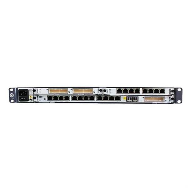
GPON is an alternative to Ethernet switching in campus networking. GPON replaces the traditional three-tier Ethernet design with a two-tier optic network which eliminates access and distribution Etherne.
[PDF]
For example, in a FTTH network, a single fiber from the telecom provider can serve 32 homes using a 1:32 splitter, eliminating the need for separate fibers to each residence. These unassuming devices enable a single optical signal to be divided into multiple paths, making them indispensable for sharing network resources efficiently—from residential FTTH (Fiber-to-the-Home) connections to large-scale telecom backbones. This guide demystifies fiber optic splitters. You use optical couplers and splitters to split or join signals in fiber networks. These devices help you control light signals well. For example, optical splitters send light to many output ports. It can divide the input optical signal into multiple output optical signals to meet the fiber optic access needs of multiple terminal devices. This type of device plays an important role in passive. A fiber-optic splitter, also known as a beam splitter, is based on a quartz substrate of an integrated waveguide optical power distribution device, similar to a coaxial cable transmission system. The optical network system uses an optical signal coupled to the branch distribution. The fiber optic. If you've ever wondered how a single fiber from your internet service provider can deliver service to an entire neighborhood or apartment building, you've wondered about the magic of optical splitters. The process of light beam splitting involves.
[PDF]
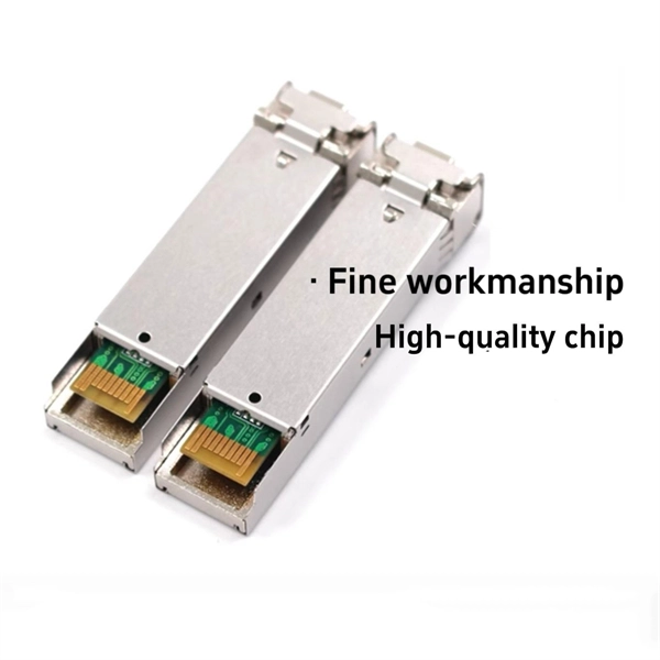
Precision begins with a quality optical encoder disc in the automation, robotics, and motion control systems of today. This tiny yet essential device transforms physical movement into exact digital signals that dictate speed, position, and direction. What constitutes an optical transceiver? An optical transceiver, a crucial device utilized in optical communication, is an optoelectronic element, allowing the interconversion of optical and electrical signals during the information transmission. It generally has the components for transmission. Therefore, NASA is developing optical communications to address limitations of radio frequency (RF) communications, including: bandwidth, spectrum and overall size of frequency packages and power used. Optical spectrum uses light as a means of transmitting information via lasers. Optical. Optical transceivers are devices that convert electrical signals into optical signals and vice versa, playing a key role in supporting modern high-speed communication networks. They are widely used in data centers and communication systems to enable high-speed, efficient transmission of large. Optical transceiver modules are designed and built by a variety of manufacturers. In the design of optical transceivers, the selection of channel configuration and modulation.
[PDF]
Commonly, a power meter on its own is used to measure absolute optical power, or used with a matched light source to measure loss. When combined with a light source, the instrument is called an Optical Loss Test Set, or OLTS, typically used to measure optical power and end-to-end optical loss.OverviewAn optical power meter (OPM) is a device used to measure the power in an signal. The term usually refers to a device for testing average power in systems. Other general purpose light power measuring. The major types are (Si), (Ge) and (InGaAs). Additionally, these may be used with attenuating elements for high optical power testing, or wavelengt. A typical OPM is linear from about 0 dBm (1 milli Watt) to about -50 dBm (10 nano Watt), although the display range may be larger. Above 0 dBm is considered "high power", and specially adapted units may measure u.
[PDF]

You are looking at $0. The price swing usually depends on the fiber count (e., 12-core vs 96-core) and brand. Generic glass is cheap; premium glass (like Corning) costs more but guarantees lower attenuation. You are looking at $0. The main price drivers include cable grade, jacket material, pull tension, connectorization, and any required conduit or protection. The following coverage gives a practical price. Fiber-optic cable materials typically cost $1 to $6 per linear foot, depending on fiber count and cable type. Commercial building installations with 100-200 network drops generally range from $15,000 to $30,000. Single-mode fiber costs less per foot than multimode fiber, but it requires more. The unit cost of fiber optic cables can vary from $0. Here's a general pricing reference: Cable TypePrice Range (USD/meter)Simplex / Duplex Indoor Cable$0. 30Single-mode Outdoor Cable$0. 50Multimode (OM1/OM2/OM3)$0. 10 –. Buyers typically pay for fiber optic cable on a per-foot or per-meter basis, plus materials, labor, and permits where applicable. Understanding cost ranges helps buyers budget. This guide outlines the major factors that influence fiber optic cable costs and provides practical tips for estimating pricing in bulk or project-based scenarios. 1 What's the Typical Price Range? 2 1. Fiber Count and Cable Construction 3 2.
[PDF]