Cable trays are mechanical support systems that provide a rigid structural system for electrical cables, raceways, and insulated conductors used for electric power distribution, control, signal instrumentation, and communication. Cable trays are used as an alternative to open wiring or electrical conduit systems, and are commonly used for cable management in. maintain spacing or to keep cables in place when the tray is ect the minimum bend ra-dius for cables as they exit the bottom of the cable tray. Metal cable trays are made of galvanized steel, stainless steel, and. The modern world relies heavily on electrical and communication cables that must be managed and supported across vast distances in commercial and industrial settings. A cable tray is an organized support structure designed to secure and route these insulated electrical cables. It acts as a. For safe application, observe the following: WARNING To prevent from shock, short-circuits or damage, observe the following: • Be sure the power is disconnected before replacement (fuse exchange, etc. • Use this product in a properly maintained condition. (Replace or repair if the body. What is a cable tray? A cable tray is a metal or non-metal structure used to lay electrical cables and wires, serving to support, protect, and guide the cables. What is the role of a cable tray in electrical engineering? A cable tray allows for the neat and aesthetic arrangement of cables.
[PDF]
A photonic integrated circuit (PIC) or integrated optical circuit is a microchip containing two or more photonic components that form a functioning circuit. This technology detects, generates, transports, and processes light. Photonic integrated circuits use photons (or particles of light) as. architecture and performance of several generations of InP-based PICs. Increased complexity in chip functionality has resulted in a need for increased fabricati n complexity from III-V epitaxy, through wafer fab, die fab, and test. Through continuous learning and improvement, Infinera has. Photonic integrated circuits (PICs) use light (photons) to transmit information, whereas traditional integrated circuits use electricity (electrons), enabling faster signal propagation. Whereas an electronic integrated circuit.
[PDF]

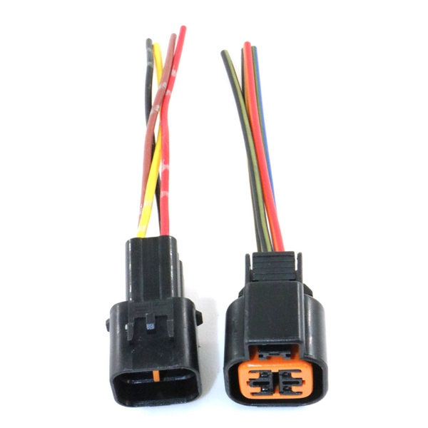
A distribution box, also known as a junction box or distribution point, is a enclosure or housing used to distribute electrical or telecommunications cables to multiple directions. A distribution box (DB box) is a key part of electrical wiring, acting as a central hub where cables branch out to various outlets and switches in a building. It supports different cable sizes and types, enabling smooth and fast power distribution. Each. Distribution boxes, also known as electrical distribution boards or panels, are pivotal components in electrical systems, ensuring the safe and organized distribution of electrical power throughout residential, commercial, and industrial environments. These boxes house various circuit breakers. With the new distribution box, centrally routed cables can be distributed 360° in all desired directions. Cables with and without connectors can be routed, sealed with IP54 (acc. to 60529) and strain relieved in accordance with EN 62444. This article will provide a detailed introduction to electrical distribution boxes, including their functions, components, types, and uses. Today, electrical systems are essential for homes and industries. But what exactly is a power distribution box, and why is it so essential in our daily lives? The DB panel board controls the flow of electricity.
[PDF]

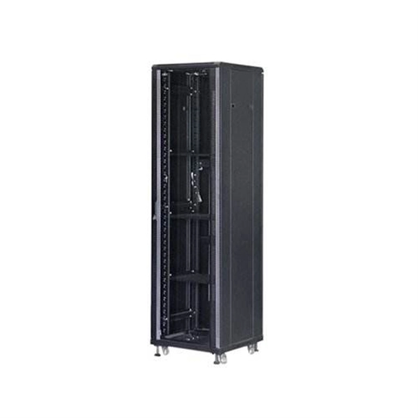
Members of the Cabinet are political appointees and administratively operate their departments. For the current cabinet, see Second cabinet of Donald Trump. The Cabinet of the United States is the principal official advisory body to the president of the United States. The Cabinet generally meets with the president in the Cabinet Room adjacent to the Oval Office in the West Wing of the White. Every President has a lot to do -- especially a modern-day United States President. He or she must: oversee dealing with foreign countries and the defense of our land. keep an eye on how our farms are doing. make sure that. The purpose of the Cabinet is to advise the President on matters relating to the duties of their respective offices. The Constitution does not directly mention a "Cabinet," but. cabinet, in political systems, a body of advisers to a head of state who also serve as the heads of government departments. The cabinet has become an important element of government wherever legislative powers have been vested in a parliament, but its form differs markedly in various countries, the. The Presidential Cabinet acts as a set of advisors for the president. What Is the US Cabinet? The US Cabinet is a series of departments within the.
[PDF]
This splice case protect fiber optic cables and juction from outside plant environment damage. They are made of reinforced ABS or PC plastic, which has high strength and corrosion resistance. In addition, the splice enclosures are all hermetically sealing structure, waterproof and. Standard polycarbonate (PC) or Glassfibre reinforced (PC+GLAS) PP ABS (Acrylnitrile-butadiene -styrene) Slightly lower UV resistance compared with PC. Recommended for outdoor use if protected against weather influences GRP – GLASS FIBRE REINFORCED POLYESTER Polycarbonate and ABS enclosure materials. The fiber optic splice closure is a closed structure used for splicing, protecting and managing optical fibers. Its material selection is crucial to ensure the quality and service life of the fiber optic splice closure. These boxes are well suited as optical cable splice collection points for DAS (Distributed Antenna Systems), MTU (Multi-Tenant Unit) commercial business applications, and MDU (Multi-Dwelling Unit). It is a reentry box which is made of PC or PP material. The shells and the base are sealed with silicone gum. This product can be re-entered and used again after it is opened. Typically selected for high-density OSP splicing and branching. What is the basic structure of Fiber Optic Splice Closure? The basic structure of Fiber Optic Splice Closure includes the box body, box components, sealing ring, and lock buckle.
[PDF]

An optical receiver is an electronic device that detects and converts optical signals into electrical signals. The primary function of an optical receiver in digital TV setups is to facilitate the transmission of high-quality audio signals between. In this architecture, optical fiber carries signals from the headend to distribution nodes across long distances, after which coaxial cable completes the final delivery to subscribers. He oversaw the day-to-day operations of the site to ensure readers have the most up-to-date information on everything from operating systems to gadgets. Prior to his current. othing beats surround sound for movies and TV — and surround sound starts with a home theater receiver. But a receiver can give you a lot more than that. During my time as a Crutchfield Sales Advisor, I helped many people choose the receiver that worked best for them. They are a step above the previously used analog audio outs. The most common types are optical and coaxial. The rest of this article will delve into how digital audio output works, how its types differ, and. When it comes to enhancing your home entertainment experience, connecting your optical TV cable to your home theater system is an essential step that can significantly elevate your audio-visual enjoyment. This guide will walk you through the process in detail, ensuring that you have all the.
[PDF]
They provide cost-effective solutions through automated dispensing and streamlined production. With the durability, robust IP67-rated protection, and resistance to vibration and environmental factors, these boxes deliver reliable performance in harsh conditions. A distribution boxes is an essential device that manages the safe and efficient flow of electrical power throughout different areas of a building or facility. It is commonly used in homes, offices, and industrial settings to control and protect electrical circuits. Understanding its significance. Many people think distribution boards and distribution boxes are the same, but they're not. They may sound similar, but they have different roles in electrical systems. Knowing the difference helps you choose the right one for your needs. But how do you choose the right one for your application? In this article, we break down the key types, core functions, and selection tips to help you make an. A distribution box, also known as a power distribution box or electrical distribution box, is used to distribute electrical power safely to multiple circuits. It helps organize, protect, and control electrical connections in residential, commercial, and industrial electrical systems. What is the distribution box? A. One critical component of a septic system is the distribution box (also called a d box). The D box is a.
[PDF]
The voltage in Turkmenistan is 230 volts and the frequency is 50 Hz. Turkmenistan has standardized on type C and type F sockets and plugs. Type E plugs can also be used thanks to their compatibility with type F sockets. If your device plugs don't match Turkmenistan's standards, we recommend purchasing suitable travel adapters in advance to ensure proper use. What power plug types are used in Turkmenistan? Plug type B. Ok, you are going to Turkmenistan, you will use power plugs/outlets similar to the following picture (s): (includes Ashgabat, Mary, Turkmenabat, Dashogus, Konye-Urgench, Turkmenbashi. (more details after you choose where. Everything you need to know about Turkmenistan power outlets, plugs for Turkmenistan, power adapters, voltage, and frequency when travelling to Turkmenistan. Planning a trip to Turkmenistan and wondering if you need a power adapter? Look no further! We've got you covered with this comprehensive. Turkmenistan uses power outlets and plugs of types C & F. Take a look at the pictures below to see what these plugs and power sockets look like: Doesn't look familiar? Do the outlets look different in your country? You'll need a power plug adapter. 220 V has an advantage over lower voltage such as the 110 V that it is cheaper to transmit. On the other hand, 220 V is more dangerous than lower voltages.
[PDF]

The main electrical appliances are refrigerator, induction cooker and microwave oven The air conditioner switch needs to be replaced, as does the main switch. The main switch does not have leakage. Because the human body passes 30mA with. A distribution box is installed under the main distribution box, and a switch box is installed under the distribution box. Electrical equipment is installed under the switch box, forming a three-level distribution. "Two level protection" mainly refers to the use of leakage protection measures. In. In a newly constructed residential area, a 10kV power line is introduced into the substation. After stepping down the voltage through the transformer's low-voltage side (0. From there, it is routed to individual building distribution boxes (secondary distribution boxes), which subsequently supply power to unit-level distribution boxes. The power distribution boxes deliver electricity from the main electrical main to other circuits. Several distribution boxes are designed for specific use in offices or industries. Main Distribution Board (MDB) 2. The distribution box serves as the load centre and distributor of electrical power. It is the central electrical supply system of any.
[PDF]

Fiber optic network diagrams represent the architecture and connectivity of fiber optic systems, and their design philosophy integrates technical, functional, and conceptual aspects. The diagrams abstract complex details of fiber optic systems to make them understandable for. Fiber optic network design refers to the specialized processes leading to a successful installation and operation of a fiber optic network. It includes first determining the type of communication system (s) which will be carried over the network, the geographic layout (premises, campus, outside. A fiber optics network diagram illustrates how high-speed data travels from an internet service provider to end users. These diagrams help engineers plan infrastructure for residential and commercial buildings. It includes detailed mapping of backbone, distribution, and drop connections for FTTH, FTTP, FTTx, and enterprise networks. Planning and design is a process that includes many decisions, involving first defining the communication protocols to be used on the network and defining geographical layout. It also involves selecting transmission equipment.
[PDF]
China is scaling domestic capabilities, with TeraHop*, Hisense, Accezlink, amongst others, shipping millions of modules to power AI interconnects. The global silicon photonics market is projected to reach $9. 2 billion by 2028, with a CAGR of 19. 4% from 2023 to 2028. Asia Pacific is expected to grow at a CAGR of 22. 1% from 2023 to 2028, driven by data center. The increasing adoption of cloud computing, artificial intelligence, and machine learning necessitates more efficient and scalable optical interconnects, where silicon photonics offers a compelling solution due to its cost-effectiveness, miniaturization, and CMOS compatibility. 4% CAGR during the forecast period (2025-2031). Silicon photonics is experiencing strong growth due to the increasing demand for high-speed data transmission in AI, cloud computing. Yole Group unveils its latest photonic market and technology analyses, Silicon Photonics 2025 and Co-Packaged Optics for Data Centers 2025, which explore how AI-driven demand is reshaping connectivity, from transceivers to packaging innovation. 200G/channel will become the new mainstream, enabling. GlobalFoundries (GF) reported fourth-quarter 2025 revenue of $1. 83 billion and highlighted silicon photonics, advanced packaging, and GaN power as central growth engines tied to AI data center buildouts. Communications infrastructure and data center revenue rose 32% year-over-year in Q4 and 29% for.
[PDF]

A perforated cable tray—also called a ventilated trough tray —features a solid bottom with regularly spaced ventilation holes and continuous side rails. Unlike ladder trays, the bottom surface provides continuous cable support, while the perforations allow limited airflow. Each cable tray type performs a different function and comes in various materials such as aluminum, galvanized steel, and FRP. What is Cable Tray? 1. Non-Metallic What is Cable. An electrical cable tray is a type of containment system used to support insulated electrical cables for power distribution, control, and communication. But what exactly is it, and why is it so important? This ultimate guide will break down everything you need to know about vertical cable trays, ensuring you. A cable tray system is a unit assembly of sections and fittings that forms a rigid structural system used to securely fasten or support cables and wiring. Think of it as a sophisticated “highway” for cables, keeping them organized, protected, and easily accessible.
[PDF]

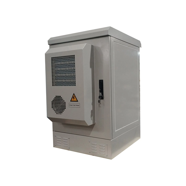
Key components typically housed within these boxes include circuit breakers, relays, fuses, and switches, all critical for safe electrical distribution in hazardous environments. Flameproof enclosure (Ex d IIB+H2), which can be used as feed distribution equipment in control and distribution system (such as distribution box, switch box of main circuit, control box, terminal box or motor starting box etc. ) ·Enclosure: stainless steel. Equipped with specialized hinge. Explosion proof equipment is designed to contain internal explosions and prevent ignition of surrounding flammable gases or dust. Rather than stopping an explosion from occurring, the equipment safely manages it within a reinforced structure. They house critical components like circuit breakers, relays, and surge protectors in durable materials such as aluminum or stainless steel. They ensure electrical safety by preventing sparks or heat from igniting flammable substances. As industries evolve, understanding how these devices operate becomes essential for engineers, safety managers, and. Explosion-proof Power Distribution Panel MAMX-02 and MAMX-03 * In-built circuit breaker, AC Contactor, Thermorelay, PLC, Transducer, Soft starter and other components, The panel can install indicator, Pushbutton, Universal switch, Display instrument. * Rated current: 1500A * Steel pipe or Cable.
[PDF]