The voltage in Turkmenistan is 230 volts and the frequency is 50 Hz. Turkmenistan has standardized on type C and type F sockets and plugs. Type E plugs can also be used thanks to their compatibility with type F sockets. If your device plugs don't match Turkmenistan's standards, we recommend purchasing suitable travel adapters in advance to ensure proper use. What power plug types are used in Turkmenistan? Plug type B. Ok, you are going to Turkmenistan, you will use power plugs/outlets similar to the following picture (s): (includes Ashgabat, Mary, Turkmenabat, Dashogus, Konye-Urgench, Turkmenbashi. (more details after you choose where. Everything you need to know about Turkmenistan power outlets, plugs for Turkmenistan, power adapters, voltage, and frequency when travelling to Turkmenistan. Planning a trip to Turkmenistan and wondering if you need a power adapter? Look no further! We've got you covered with this comprehensive. Turkmenistan uses power outlets and plugs of types C & F. Take a look at the pictures below to see what these plugs and power sockets look like: Doesn't look familiar? Do the outlets look different in your country? You'll need a power plug adapter. 220 V has an advantage over lower voltage such as the 110 V that it is cheaper to transmit. On the other hand, 220 V is more dangerous than lower voltages.
[PDF]

A perforated cable tray—also called a ventilated trough tray —features a solid bottom with regularly spaced ventilation holes and continuous side rails. Unlike ladder trays, the bottom surface provides continuous cable support, while the perforations allow limited airflow. Each cable tray type performs a different function and comes in various materials such as aluminum, galvanized steel, and FRP. What is Cable Tray? 1. Non-Metallic What is Cable. An electrical cable tray is a type of containment system used to support insulated electrical cables for power distribution, control, and communication. But what exactly is it, and why is it so important? This ultimate guide will break down everything you need to know about vertical cable trays, ensuring you. A cable tray system is a unit assembly of sections and fittings that forms a rigid structural system used to securely fasten or support cables and wiring. Think of it as a sophisticated “highway” for cables, keeping them organized, protected, and easily accessible.
[PDF]

Protective relays are special electrical devices used to detect faults in power systems and quickly disconnect faulty parts to prevent damage. These relays sense abnormal conditions like overcurrent, under-voltage, or short circuits and send a signal to circuit breakers to open the. Electromechanical protective relays at a hydroelectric generating plant. The relays are in round glass cases. The rectangular devices are test connection blocks, used for testing and isolation of instrument transformer circuits. In electrical engineering, a protective relay is a relay device. Protective Relay Definition: A protective relay is an automatic device that senses abnormal conditions in electrical circuits and triggers actions to isolate faults. Types of Protective Relays: Protective relays are categorized by their mechanism (electromagnetic, static, mechanical) and function. Combines protection, sensors, control power, and circuit breaker in a single package Typically added to a breaker close circuit to prevent accidental reclosure after a trip. Three fundamental components required for each circuit breaker. It initiates the operation of circuit breakers to isolate the affected section.
[PDF]
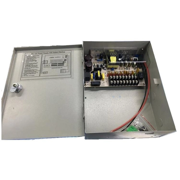
They provide cost-effective solutions through automated dispensing and streamlined production. With the durability, robust IP67-rated protection, and resistance to vibration and environmental factors, these boxes deliver reliable performance in harsh conditions. A distribution boxes is an essential device that manages the safe and efficient flow of electrical power throughout different areas of a building or facility. It is commonly used in homes, offices, and industrial settings to control and protect electrical circuits. Understanding its significance. Many people think distribution boards and distribution boxes are the same, but they're not. They may sound similar, but they have different roles in electrical systems. Knowing the difference helps you choose the right one for your needs. But how do you choose the right one for your application? In this article, we break down the key types, core functions, and selection tips to help you make an. A distribution box, also known as a power distribution box or electrical distribution box, is used to distribute electrical power safely to multiple circuits. It helps organize, protect, and control electrical connections in residential, commercial, and industrial electrical systems. What is the distribution box? A. One critical component of a septic system is the distribution box (also called a d box). The D box is a.
[PDF]

This report lists the top Fusion Splicer companies based on the 2023 & 2024 market share reports. Mordor Intelligence expert advisors conducted extensive research and identified these brands to be the leaders in the Fusion Splicer industry. Fujikura Europe Ltd offers fusion splicers, which are essential for efficiently joining optical fibers. As the official support center for Fitel splicers, OFS. AFL - Fiber optic cable, transmission and substation accessories, outside plant equipment, connectors, fusion splicers, test and inspection equipment. Discover how these fusion-spliced, field-installable connectors simplify installation and improve performance. Are you looking for a professional and reliable fiber optic products manufacturer for your business? Are you still worried about how to find and select a best partner from so many fiber optic products manufacturers? Don't be afraid, Gcabling will help you. In this post, Gcabling, as a professional. Fiber splicing is the process of joining optical fibers to create continuous, low-loss optical pathways used in manufacturing, research, and high-performance fiber systems. In advanced applications, fiber splicing is not a single operation. They are headquartered in locations across the globe, including the United States, China, Brazil, and India, with founding years ranging from 1964 to 2019.
[PDF]
A photonic integrated circuit (PIC) or integrated optical circuit is a microchip containing two or more photonic components that form a functioning circuit. This technology detects, generates, transports, and processes light. Photonic integrated circuits use photons (or particles of light) as. architecture and performance of several generations of InP-based PICs. Increased complexity in chip functionality has resulted in a need for increased fabricati n complexity from III-V epitaxy, through wafer fab, die fab, and test. Through continuous learning and improvement, Infinera has. Photonic integrated circuits (PICs) use light (photons) to transmit information, whereas traditional integrated circuits use electricity (electrons), enabling faster signal propagation. Whereas an electronic integrated circuit.
[PDF]
Flex electrical cable, often referred to as flexible cable or flex, is a type of wire that is designed to withstand repetitive bending and movement without damage. Article 400 covers the general requirements and applications for flexible cords as contained in Table 400. A “flexible cord” is two or more insulated conductors enclosed in a flexible covering. Figure 01 The NEC does not. What is a flexible cable? Flexible cables are cables that have multiple conductors (Class 5 or Class 6 conductors) that form the conductor and are insulated and sheathed in a lightweight, flexible material (usually plastic or rubber). Why choose flexible cables for domestic use? It is suitable for. These include flat flexible cable (FFC), stranded wire, power cables, control cables, and flexible electrical conduit. Each type meets specific needs across industries like automotive, electronics, and medical devices. Here is a quick look at how leading cable types are used worldwide: You can. Power distribution cables present a unique challenge to electrical wire interconnect system engineers. Unlike rigid electrical wiring, which is designed for static installations within buildings, walls, or. In any electrical system—whether powering lights in homes, machinery in factories, or robots in operation—cables are the unsung heroes, safely and reliably transmitting electrical energy. As the backbone of power distribution systems, cables connect power sources (such as circuit breakers) to.
[PDF]

Circuit breaker wiring configurations involve organizing main switches, busbars, and branch breakers within a distribution box. Proper setups ensure balanced electrical loads, ground fault protection, and easy maintenance. Messy distribution boxes are dangerous and very hard to fix. This guide shows you how to organize circuit breaker wiring properly. You will learn to build a safe, efficient, and professional electrical system today. Location determination: Determine the installation position of the circuit breaker according to the position of the. The distribution board is the heart of every electrical installation. This guide covers split load vs dual RCD vs RCBO board configurations, circuit arrangement and allocation, BS 7671 labelling requirements, type testing under BS EN 61439, SPD installation, wiring best practice, and the common. Distribution panels, breaker panels, load center, and/or distribution boards—any name you call them, they're a key part of every electrical system. Wiring distribution panels serve as the central hub and nerve center, routing power from the main service feed to multiple circuits. When setting up. Hey, in this article we are going to see the Single Phase Distribution Box Wiring Diagram and Connection Procedure. It serves as a central hub for distributing electricity throughout a building, ensuring that power is delivered safely and efficiently to all the required locations.
[PDF]

Link Aggregation is a generic term for combining multiple network connections to work as one logical connection. It is standardized under the IEEE 802. So, what exactly is an aggregation switch, and how do you choose the right one? Let's examine it in detail. What Is an Aggregation Switch? An aggregation switch is a network device that consolidates traffic from multiple access switches, wireless access points, or other edge devices and forwards it. Is a Aggregation switch just to connect different networks? I have all my Clients wired into the USW Pro this is connected to the UDM by 10g fibre. The NVR is connect via Fibre to the USW as well. So. ? Any hints welcome! Archived post. New comments cannot be posted and votes cannot be cast. The primary function of an aggregation switch is to aggregate and forward data. Link Aggregation, Port Channel, and EtherChannel are related concepts in networking that involve combining multiple physical network links into a single logical link to increase bandwidth, redundancy, and fault tolerance. Let's break them down: 1. A round-robin algorithm is used for load balancing traffic across the interfaces in an aggregated link. Dynamic Link Aggregation (LACP) has been introduced on SonicOS 6. Link. LAG simplifies controller configuration by eliminating the need to configure ports for each interface. If any controller port fails, traffic migrates automatically to other functioning ports. Wireless clients.
[PDF]

The main electrical appliances are refrigerator, induction cooker and microwave oven The air conditioner switch needs to be replaced, as does the main switch. The main switch does not have leakage. Because the human body passes 30mA with. A distribution box is installed under the main distribution box, and a switch box is installed under the distribution box. Electrical equipment is installed under the switch box, forming a three-level distribution. "Two level protection" mainly refers to the use of leakage protection measures. In. In a newly constructed residential area, a 10kV power line is introduced into the substation. After stepping down the voltage through the transformer's low-voltage side (0. From there, it is routed to individual building distribution boxes (secondary distribution boxes), which subsequently supply power to unit-level distribution boxes. The power distribution boxes deliver electricity from the main electrical main to other circuits. Several distribution boxes are designed for specific use in offices or industries. Main Distribution Board (MDB) 2. The distribution box serves as the load centre and distributor of electrical power. It is the central electrical supply system of any.
[PDF]

Fiber optic network diagrams represent the architecture and connectivity of fiber optic systems, and their design philosophy integrates technical, functional, and conceptual aspects. The diagrams abstract complex details of fiber optic systems to make them understandable for. Fiber optic network design refers to the specialized processes leading to a successful installation and operation of a fiber optic network. It includes first determining the type of communication system (s) which will be carried over the network, the geographic layout (premises, campus, outside. A fiber optics network diagram illustrates how high-speed data travels from an internet service provider to end users. These diagrams help engineers plan infrastructure for residential and commercial buildings. It includes detailed mapping of backbone, distribution, and drop connections for FTTH, FTTP, FTTx, and enterprise networks. Planning and design is a process that includes many decisions, involving first defining the communication protocols to be used on the network and defining geographical layout. It also involves selecting transmission equipment.
[PDF]
Photovoltaic modules, or solar modules, are devices that gather energy from the sun and convert it into electrical power through the use of semiconductor-based cells. A photovoltaic module contains numerous photovoltaic cells that operate in tandem to produce electricity. A single PV device is known as a cell. An individual PV cell is usually small, typically producing about 1 or 2 watts of power. These cells are made of different. Photovoltaics (PV) is the conversion of light into electricity using semiconducting materials that exhibit the photovoltaic effect, a phenomenon studied in physics, photochemistry, and electrochemistry. Here is a description of their main features and of Enel Green Power's innovative solution. A semiconductor.
[PDF]

Every fiber optic patch cable has a rated attenuation and bandwidth. For example, OM1 is rated at 200 MHz·km at 850 nm and is intended for use in legacy applications. The higher OM ratings provide more speed and distance. Attenuation should remain within acceptable limits for reliable transmission. Executive Summary: Choosing the right fiber patch cable is one of the most consequential decisions in network infrastructure planning. The wrong choice — whether it's an underperforming multimode grade or an unnecessarily expensive singlemode run — can either cripple your network's reliability or. Fiber optic patch cords are key components for efficient, low-loss optical signal transmission between devices and fiber optic cabling links. One or both ends of the patch cord are equipped with standardized fiber optic connectors, and common interfaces include LC, SC, FC, ST, etc. They are manufactured and tested in compliance with TIA 604 (FOCIS), IEC 61754 and YD/T industry standards. OM1, OM2, OM3, OM4, OM5 or OS2 fiber types are available to meet the demand of. Fiber optic patch cables are ideal for supporting high speed telecommunication network fiber applications. They are lengths of optical fiber terminated with connectors on both ends. Their job is to connect two optical devices, like switches, routers, or optical transceivers that communicate.
[PDF]